Racing the Beam
Racing the Beam. Dan’s MEGA65 Digest for May 2024.
At least once before in this Digest I’ve said something about how there’s a way to write a program to perform precisely timed actions, but the actual technique would have to wait until a future issue. In this issue, we’ll start looking into this, with a focus on synchronizing a program with a particularly useful hardware feature: the raster beam.
To do this effectively, we’ll introduce an important programming paradigm supported directly by a feature of the CPU, called interrupts. To get that to work, we’ll also take a brief look at how to uninstall the KERNAL operating system by changing the system’s memory map.
Any news?
Trenz Electronic is busily assembling new MEGA65s, still on track for delivering the next batch in the next few weeks. The Discord and Forum64 board have been quieter than usual, with everyone starting new projects or resting up from previous ones. I can’t wait for the rush of new people joining and asking questions!
If you have a project in progress that you’d like to see featured in the Digest, let me know! You can also announce your project in the #announcements channel on the Discord, and upload your work in progress to Filehost for others to try. Beginners welcome! Some of the coolest stuff we’ve seen for the MEGA65 has been written in BASIC by people like you just trying things out.
The time keepers
Every computer contains a component that generates a clock signal, a fast and precisely timed electronic pulse that drives the digital devices in the computer. Like turning the crank of a music box, these pulses advance the internal mechanisms of each device through their various stages to perform computations, and to generate signals of their own. The clock signal also synchronizes the devices with each other, so they can communicate with one another over their electronic connections.
MEGA65 programs can take advantage of three specific devices driven by the system clock to execute code with precise timing: the CPU, the VIC video chip, and the CIA chip.
The CPU
The CPU uses the clock signal to perform the machine code instructions of a program. Each instruction requires a certain number of cycles to perform, where each cycle takes a fixed amount of time based on the clock. For example, the lda #$ff instruction, which loads the byte value $ff from the program code into the accumulator register, takes two CPU cycles to complete. The cycle cost of an instruction depends on the instruction and addressing mode, but it’s typically between 1 and 6 cycles, and as many as 14 cycles for fancier operations like the 45GS02 Q-register instructions.
In its default MEGA65 mode, the MEGA65 CPU performs instructions at 40.5 million cycles per second, or 40.5 megahertz (MHz). The MEGA65 can also underclock its cycle rate to emulate a Commodore 64 (1 MHz), Commodore 128 (2 MHz), or Commodore 65 (3.5 MHz).
In theory, you can analyze the duration of a section of machine code by looking up the cycle costs of each instruction and adding them together. Commodore 64 programmers sometimes do this to optimize small sections of code, especially for advanced video effects that require precise coordination between the 1 MHz CPU and the VIC video chip. This is less necessary with the MEGA65’s 40.5 MHz CPU, which outpaces most of the signal frequencies that a program might care about.
A program can pause for a period of time by executing instructions and ignoring the results, simply to burn through cycles. This could be a series of instructions in memory, a loop with a counter, or a loop that exits when a hardware register changes. This technique is known as busy-waiting because the CPU can’t stop executing instructions: it has to twiddle its thumbs to keep busy—and also to figure out when to stop waiting and continue the program.
Try these examples of busy-waiting in BASIC:
5 REM -- PAUSE BRIEFLY BY DOING NOTHING IN A LOOP
10 BORDER 0
20 FOR A=1 TO 20000
30 NEXT A
40 BORDER 1

5 REM -- WAIT FOR JOYSTICK FIRE BUTTON, PORT 1
10 BORDER 0
20 IF (JOY(1) AND 128)=0 THEN 20
30 BORDER 1
The VIC
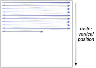
The VIC video chip uses the system clock to generate a video signal with the precise timing expected by the display hardware. Such protocols are derived from old cathode-ray tube (CRT) displays that draw the entire screen with a beam of electrons. This raster beam sweeps across the screen in a fixed pattern of horizontal rows, or raster lines, from left to right, top to bottom. The video signal controls the intensity of the beam, and the beam leaves pixels in its wake that form the complete image. Once it reaches the bottom, the beam returns to the top of the screen, and the process repeats, many times per second.
The MEGA65 connects to modern VGA analog or HDMI digital displays. Internally, it attempts to recreate the display parameters of one of two vintage analog video modes, either PAL or NTSC, so that vintage software that depends on these parameters will run properly. The PAL video mode draws 312 raster lines 50 times per second, also known as a refresh rate of 50 Hz. NTSC draws 262 lines 60 times per second, or a refresh rate of 60 Hz. A full image consists of two interlaced sets of lines, so the actual image size and frame rate is twice as many lines and half the frequency: PAL video is 625 lines tall with a frame rate of 25 Hz.
Synchronizing a program’s behavior with the raster beam is a powerful way to perform advanced visual effects. By changing VIC control parameters at specific times during the drawing of the screen, a program can break away from some of the VIC’s numerical limitations. This is the basis for one of the most coveted of Commodore graphical techniques, called sprite multiplexing, where the VIC’s eight hardware sprites are reused in different parts of a single screen.
The CIAs
The Complex Interface Adapter (CIA) chip is a multi-purpose chip that manages device and serial communications, and also has a high-precision countdown timer feature. Each CIA chip contains two timers, and the MEGA65 (like the Commodore 64) has two CIA chips, each wired up a bit differently. The CIA counts pulses at a rate of 1 MHz, and your program can set a timer interval up to 65,535 of these pulses, for a delay of up to approximately 0.065 seconds. For example, to set a timer for 1/60th of a second, your program would set the timer value to 16,666.
We’ll save a complete discussion of the CIA chip for another time. For now, suffice it to say that you can use both busy-waiting and interrupt-based techniques with the CIA high-precision timers.
Other clocks
There are two other kinds of clock that are worth knowing about, but are less useful for high-precision timing. Each CIA chip contains a time-of-day (TOD) clock that counts tenths of seconds, seconds, minutes, and hours, up to a 24-hour period. In the Commodore 64, this clock powers the TI and TI$ BASIC variables, and is reset to midnight when the computer is switched off. The MEGA65 contains a separate battery-backed Real-Time Clock (RTC) chip that can remember the time of day and calendar date even when power is disconnected. BASIC 65 uses the RTC chip for the TI$ and DT$ variables, and it uses the CIA TOD clock for the TI variable.
Just to complete the picture, here’s a simple BASIC program that busy-waits on the TI special variable for three seconds. Notice that the TI variable’s value changes over time, even though the BASIC program itself isn’t changing it.
5 REM -- WAIT 3 SECONDS
10 BORDER 0
20 T=TI
30 IF (TI-T)<3 THEN 30
40 BORDER 1
Finding the beam
The VIC video chip generates a signal for the raster beam to draw onto the display, expecting the raster beam to follow a fixed pattern on a regular interval. The VIC keeps track of where the raster beam is located, and a program can access this information by reading a hardware register.
One way to synchronize a program’s behavior with the VIC’s raster beam is to busy-wait on its location. You can do this from BASIC 65, with the VSYNC command:
10 BORDER 0
20 VSYNC 100
30 BORDER 1
40 VSYNC 200
50 GOTO 10
VSYNC pauses the BASIC program and busy-waits for the raster beam to reach a given vertical position (or raster line). The vertical position number can be between 0 and 311 in PAL video mode, or 6 and 261 in NTSC mode, where smaller numbers are further up the screen. Try adjusting the numbers on lines 20 and 40 in this example program. (Beware that there’s currently a bug that causes VSYNC to hang with a value less than 6 in NTSC mode.)
Here is an equivalent program in assembly language. Because the raster beam vertical position can be larger than 255, it takes up more than one byte of space across two register addresses. Bit 7 of register $D011 is high (1) if the raster beam is beyond line 255.
vicii_rcl = $d012
vicii_rch = $d011  ; bit 7
border = $d020

loop:
    lda #0  ; black
    sta border

    lda #100
-   cmp vicii_rcl
    bne -
    bit vicii_rch
    bmi -  ; rch is high, not our stop

    lda #1  ; white
    sta border

    lda #200
-   cmp vicii_rcl
    bne -
    bit vicii_rch
    bmi -  ; rch is high, not our stop

    jmp loop
$D011/$D012 are the VIC-II raster position registers. Indeed, this example will work on a Commodore 64 as well as the MEGA65. The MEGA65’s VIC-IV is also capable of doubling the vertical resolution of the screen, a mode known as “V400,” which uses twice as many raster lines. You can see this mode in action by activating the 80x50 text mode: press Esc then 5. (Press Esc then 8 to return to 80x25 text mode.) In V400 mode, the $D011/$D012 VIC-II registers and the VSYNC command continue to use the raster position as if it were in the non-doubled mode, so the bottommost VIC-II raster position in PAL video mode is still “312,” even if V400 is active. If you want the actual mode-specific VIC-IV raster position, an 11-bit value, see the FNRASTERLSB register at $D052 (lower 8 bits) and FNRASTERMSB at $D053.0-2 (upper 3 bits).
Note that while the raster vertical position corresponds to pixel Y-coordinates, the beam starts well above the top edge of the usual background area inside the colored border—because the raster beam also draws the border! The outermost raster positions are outside of the visible area.
Visualizing time
The ability to synchronize our program with the raster beam gives us a clever way to visualize the duration of a section of program code—using the border color! Try this:
10 N=30
20 DIM FB(N):FB(0)=0:FB(1)=1

60 FOR I=2 TO N
70 FB(I)=FB(I-2)+FB(I-1)
80 NEXT I
This program allocates an array of 30 numbers, then fills it with the Fibonacci sequence. To see this in action, run the program, then type: PRINT FB(5)
We can get a sense of how fast this code runs using a combination of VSYNC and BORDER, like so:
10 N=30
20 DIM FB(N):FB(0)=0:FB(1)=1

30 BORDER 0
40 VSYNC 100
50 BORDER 1

60 FOR I=2 TO N
70 FB(I)=FB(I-2)+FB(I-1)
80 NEXT I

90 GOTO 30
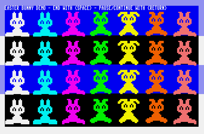
The Fibonacci code is the same, but now it runs repeatedly in a loop. For each repetition, the program changes the border color to black, synchronizes to raster line 100, changes the border to white, then performs the Fibonacci fill. When control loops back to line 30, the border is changed back to black. In other words, the border is only white for the time it takes to fill the array. The height of the white bars in the border represent how far the raster beam travels during the fill operation. The VSYNC command makes sure this happens when the raster beam is at the same spot on the screen every time, to hold the white bars steady.
Try changing N in line 10 to another number, such as N=5 or N=40. This changes the size of the array, and therefore changes the amount of time it takes to fill it with Fibonacci numbers.
Caution: This next step causes the screen to flicker. Change line 10 to N=80, then run the program. Press Run/Stop to stop the flickering.
Why does the screen flicker when N=80? Here’s what’s happening:
- The raster beam reaches position 100, the border changes to white, then the Fibonacci algorithm runs while the raster beam travels.
- In the time it takes to calculate 80 Fibonacci numbers, the raster beam reaches the bottom of the screen, returns to the top, then goes just beyond position 100.
- The Fibonacci fill completes, and the program changes the border back to black—but by now the raster beam has made it all the way through the screen and has drawn an entirely white border.
- The program waits for the raster beam to reach 100 again, which requires the raster beam to travel through almost a full screen with the border color set to black. With each screenful alternating between black and white, the border flickers.
Visualizing code duration using the border color is especially helpful when writing games and demos. To animate graphics smoothly, a game must update all of the screen data in less than the time it takes to draw a single screen, so the updated data is ready for the next pass of the raster beam. If the border flickers, it means the computation is taking up more than one screen’s worth of raster travel, and the programmer has some work to do.
Wherefore interrupts?

A typical machine code program is a sequence of instructions performed one at a time by the CPU in the order the instructions are given. Branching instructions can change the flow of control to other instructions in memory, but otherwise the CPU just marches down the list.
An interrupt is an event in a computer that needs immediate attention from the software. The event can come from a peripheral, such as a key press or incoming serial communication, or an internal programmable device that isn’t the CPU, such as the VIC or CIA chip. (As a special case, an interrupt event can also be triggered directly by the software with the brk instruction, but we’ll ignore this for now.)
When an interrupt occurs, the CPU completes the current instruction (however many cycles are remaining), stops executing the program, then calls a software routine called an interrupt handler. A typical interrupt handler does a small amount of work to respond to the event, then resumes the main program where it left off.
Interrupts allow a program’s code to be organized as if it were two programs: a main program that runs as if it is unaware that special events are occurring, and a short program that runs whenever a special event occurs. Without interrupts, a program would have to be written in such a way as to check for the special condition periodically, in between doing everything else it needs to do. This can delay the program’s ability to respond to the event, or even cause it to miss the event entirely.
Here’s a quick demonstration in BASIC of what could go wrong in this scenario. The program loop does some “work” that takes time, in this case an empty loop, but imagine it’s doing something important. Once the program has a free moment, it checks to see if the fire button of the joystick in port 1 is pressed; if not, it goes and does some more work. It’s pretty difficult to get this program’s attention with the fire button. Only by holding the button down will it eventually notice and respond.
10 BORDER 0
20 REM -- DO SOME "WORK"
30 FOR A=1 TO 50000
40 NEXT A
50 REM -- CHECK FOR FIRE BUTTON IN JOYSTICK PORT 1
60 IF (JOY(1) AND 128)=0 THEN 30
70 BORDER 1
You can imagine a hypothetical computer that triggers an interrupt when the fire button is pressed, halting the “work” to respond immediately. Because interrupts are built into the hardware, only a few kinds of events are wired into the CPU interrupt system. A typical program would use one of the timing sources (VIC or CIA) to trigger an interrupt at fixed intervals many times a second, and the interrupt handler would check for things like joystick input and react accordingly. This is how the KERNAL moves sprites or plays music concurrently with a BASIC program, or blinks the cursor while waiting for keyboard input at the READY. prompt. The steady drumbeat of interrupts allows the program (or the KERNAL) to respond to user input quickly, and progress animation and music smoothly.
Custom interrupt handlers are exclusively the domain of machine code programs. While BASIC programs benefit from how the KERNAL uses interrupts, they can’t use interrupts directly. In most cases, the best a BASIC game program can do is keep the game loop logic short and fast, so it can respond to joystick input as soon as possible. So maybe don’t loop 50,000 times between checks for the fire button.
BASIC 65’s sprite COLLISION feature behaves like an interrupt handler, but it’s actually implemented by the BASIC interpreter, not the CPU’s interrupt system: the interpreter just checks for sprite collisions before executing each BASIC statement.
IRQs and NMIs

The 6502 family of CPUs supports two kinds of interrupt: an interrupt request (IRQ), and a non-maskable interrupt (NMI). Some events trigger IRQs, and others trigger NMIs.
The difference between IRQs and NMIs is that certain CPU operations can temporarily disable IRQs, and a program can disable and re-enable IRQs as needed, while NMIs cannot be disabled. Disabling IRQs is like putting a “Do Not Disturb” sign on a hotel room door: it says that the main program is working on something that should not be interrupted, and interrupt requests should be ignored for the time being. NMIs are more like a hotel fire alarm: they must be handled immediately, no matter what. Both kinds of interrupt are necessary for a fully functioning system, but most programs can get away with only dealing with IRQs.
The following are possible sources of IRQ interrupts in the C64 and MEGA65:
- VIC raster beam location
- VIC sprite collision
- Timers on CIA #1
- The
brkinstruction
The following are possible sources of NMI interrupts in the C64 and MEGA65:
- Timers on CIA #2
- RS-232 serial communication
- Pressing the Restore key
Yes, pressing the Restore key triggers the NMI handler! This is how Run/Stop + Restore works: the KERNAL’s NMI handler tests whether both keys are pressed, then resets BASIC and declines to continue the interrupted program. This works even if the program has disabled IRQs.
The CPU supports one interrupt handler for IRQs and one handler for NMIs. It’s up to the handler code to figure out the specific cause of the interrupt, and react appropriately.
The address of each interrupt handler is stored as two bytes, in little-endian order (low byte first), at a fixed 16-bit address: the IRQ handler address is stored at $FFFE-$FFFF, and the NMI handler address is stored at $FFFA-$FFFB. The MEGA65’s default memory map installs KERNAL ROM code in this location, and the KERNAL uses its own interrupt handlers, so you can’t just POKE new addresses here. One way that a program can install custom interrupt handlers is to uninstall the KERNAL, by changing the memory map.
It is possible to leave the KERNAL in place and ask it to call custom code during its own IRQ handler. We’re still formalizing and documenting KERNAL integration techniques, so this is best left alone for now when writing MEGA65 programs. This is probably the most popular KERNAL integration technique on the C64, so we’ll try to finish this soon. (Hint: use the “VECTOR” KERNAL routine.)
For the rest of this Digest, we’ll focus on the raster beam IRQ, and assume that the program will uninstall the KERNAL to install its own handler. We’ll save other interrupt types for another time.
Interrupt handlers
When the CPU encounters an IRQ, it finishes the current instruction, then pushes the 16-bit address of the next instruction onto the stack (two bytes). It also pushes the CPU flags onto the stack, as a single byte. It then disables IRQs, then jumps to the address stored in the IRQ vector.
The first thing the interrupt handler needs to do is preserve any additional CPU state that might get clobbered by the rest of the handler. The main program expects everything about the CPU to be just as it left it, including the values in other registers. For example, if the handler needs to use the accumulator (and it probably does), it needs to push the previous accumulator value to the stack beforehand, and restore it afterward.
For most kinds of IRQ interrupt, the device that triggers the interrupt stays in the “interrupt” state until it is told that the interrupt is handled. The program must interact with the device via a hardware register to acknowledge the interrupt, so that it doesn’t re-trigger once the interrupt handler resumes the program. Remember that an IRQ can have multiple causes, so if your program enables more than one cause, it will need to determine the cause and handle it appropriately.
When the interrupt handler is complete, it calls the rti instruction to resume the paused program. This restores the CPU flags and next code address from the stack (thereby re-enabling interrupts), and continues where it left off. This is kind of like how jsr jumps to a subroutine and rts returns from it, with minor differences. For example, normal subroutines don’t stash and restore the CPU flags.
irq_handler:
    ; Preserve the Accumulator, X, Y, and Z registers
    ; on the stack.
    pha
    phx
    phy
    phz

    ; Test for and acknowledge the IRQ cause...

    ; Do something fun...

    ; Restore the CPU registers, pulling them off the
    ; stack in the reverse order they were pushed.
    plz
    ply
    plx
    pla

    ; Resume the program
    rti
Enabling and disabling IRQs
The CPU keeps track of whether IRQs should be handled or ignored using the “IRQs disabled” CPU status flag (I). To disable IRQs, a program calls the sei instruction (“set IRQ disabled”). To re-enable IRQs, a program calls the cli instruction (“clear IRQ disabled”). I know, this set/clear definition feels like a double-negative; just think of how interrupts being enabled is the default case (0 or clear), and being disabled is the special case (1 or set).
The CPU will automatically disable IRQs when calling either the IRQ or NMI interrupt handler, so an IRQ handler can’t re-trigger while it is executing, nor can a handler be interrupted by something else. Interrupts get re-enabled automatically when the rti instruction restores the previous status flags from the stack. It’s possible to get fancy with this, and some advanced techniques make unusual exits from the interrupt handler or manipulate the stack.
Interrupts are also disabled automatically while updating the 45GS02 memory map registers. This is important because memory map adjustments require several instructions, and interrupting these instructions could be disastrous if the incomplete memory map leaves either the interrupt handler code or handler vectors in an inconsistent state.
This is an important hint for how a program and its interrupt handlers can communicate with each other. If the main program is updating the state of the system, and it’d be bad if the interrupt handler sees the state only partially updated, the main program should disable interrupts (sei), update the state, then re-enable interrupts (cli). Remember: with interrupts enabled, the handler could be called between any two instructions, including between an lda and an sta. Modern-day programmers might compare disabling interrupts to a “global lock” on memory and CPU state, albeit a simple one.
Setting up hardware interrupt handlers
Let’s try disabling the KERNAL and setting up our own interrupt handler. This requires a few steps.
We’re not going to cover memory mapping in detail in this issue. To learn more about it, download the latest version of The MEGA65 Compendium and check out the “Memory” chapter. For now, we just need to know a few things:
- The MEGA65 has an address space of 28 bits, with addresses numbered from $000.0000 to $FFF.FFFF. Some of these addresses go to memory, some go to hardware registers, and some are unassigned.
- The CPU sees 64KB of the MEGA65’s memory at a time, using 16-bit addresses numbered from $0000 to $FFFF.
- The CPU maintains a memory map that assigns 8KB chunks of the 16-bit address space to the 28-bit address space. A program can adjust this memory map using CPU instructions.
The MEGA65 KERNAL ROM code lives in the 28-bit address space from $2.0000 to $3.FFFF. While the KERNAL is running, it switches between a few memory maps to do various things. Most importantly, when interrupts are enabled, the 28-bit addresses $3.E000 to $3.FFFF are mapped to 16-bit addresses $E000 to $FFFF, which includes the IRQ and NMI vectors as well as the handler routines that they point to.
To take this over for our own purposes, we need to reset the memory map so that $E000 to $FFFF points to RAM at $0.E000 to $0.FFFF. The memory map consists of eight bytes of information. Without going into detail, we can accomplish our task by setting four of these bytes to zero. To do this, set the A, X, Y, and Z registers to zero, then use the map instruction, followed by the eom (“End Of Map”) instruction:
    lda #0
    tax
    tay
    taz
    map  ; Disable IRQs and update the MAP register

    eom  ; End MAP adjustments, re-enable IRQs
The map instruction transfers A, X, Y, and Z to the first four bytes of the MAP register. Simultaneously, the map instruction also disables IRQs (similar to sei). After the first map and before the eom, the program can call map a second time to set the second four bytes of the MAP register if needed, or otherwise set up any additional state needed by IRQ handlers in the new memory map. The eom instruction signifies that the MAP setting is complete, and re-enables IRQs.
The map and eom instructions are specific to the 65CE02 CPU on which the 45GS02 is based, so you’ll want to use an assembler that supports them, like Acme assembler. If your assembler of choice only supports CPUs up to the 65C02, you can use the aug instruction for map, and nop for eom. If your assembler only supports 6502 instructions, get a better assembler.
The KERNAL keeps the VIC raster interrupt active for its own purposes, so we need to either disable this or set it up the way we want. In general, it’s a best practice to disable all sources of interrupt that your program doesn’t recognize when installing custom interrupt handlers.
Let’s use the gap between map and eom to install our own interrupt handlers, and disable the KERNAL’s raster interrupt. Even though we’re not discussing NMIs for now, we need an NMI handler because we’re replacing all of the KERNAL’s handlers. (We’ll look at a more thorough way to do this another time.)
hw_nmi_vec = $fffa
hw_irq_vec = $fffe
vicii_irqmask = $d01a
ciaa_d = $dc0d
ciab_d = $dd0d

    lda #0
    tax
    tay
    taz
    map  ; (disables interrupts)

    ; Set the NMI handler vector
    lda #<nmi_handler
    sta hw_nmi_vec
    lda #>nmi_handler
    sta hw_nmi_vec+1

    ; Set IRQ handler vector
    lda #<irq_handler
    sta hw_irq_vec
    lda #>irq_handler
    sta hw_irq_vec+1

    ; Disable all VIC IRQs
    lda #0
    sta vicii_irqmask

    ; Disable all CIA IRQs, and acknowledge any pending timers
    lda #$7f
    sta ciaa_d
    sta ciab_d
    lda ciaa_d
    lda ciab_d

    ; Set up the interrupts we care about...

    eom  ; (re-enables interrupts)

    ; Main program...
-   bra -  ; (Just an empty busy-loop for now.)

irq_handler:
    pha

    ; Test for and acknowledge the IRQ cause...

    ; Do something fun...

    pla
    rti

nmi_handler:
    rti
Raster interrupts
The VIC chip can trigger an IRQ when the raster beam is at a requested position. Setting this up requires two simple steps.
First, the program must tell the VIC what raster position to use. As with the BASIC 65 VSYNC command, the range of this value depends on the video mode: 0 to 311 for PAL, and 6 to 261 for NTSC. The program sets the desired location with the lower eight bits in register $D012, and the ninth bit as bit 7 of register $D011.
Astute readers may notice that this is the same register we used to read the raster position for busy-waiting! The VIC is clever enough to re-use this register location in this way: when you read the register, it returns the current raster position. When you write to the register, you set the raster interrupt position.
The second step is to set a flag that says the program wants the VIC to trigger the raster IRQ. Set bit 0 of register $d01a to 1 to enable the raster IRQ.
vicii_rcl = $d012
vicii_rch = $d011  ; bit 7
vicii_irqmask = $d01a

    ; Enable raster interrupt at position 200
    lda #200
    sta vicii_rcl
    lda vicii_rch  ; clear bit 7 of $d011
    and #$7f
    sta vicii_rch
    lda #$01
    sta vicii_irqmask
Within the IRQ handler, you can confirm that it was the raster IRQ that triggered the interrupt by testing bit 0 of register $D019. To acknowledge the interrupt and prevent the IRQ handler from re-triggering, write a 1 to this bit. This is another register that has unusual read and write behavior: reading it tests the IRQ trigger status, and writing a 1 to a bit “unlatches” the trigger.
vicii_irq = $d019

irq_handler:
    pha

    ; Test for raster IRQ
    lda vicii_irq
    bit #$01
    beq +  ; not raster IRQ

    ; Acknowledge raster IRQ
    lda #$01  ; write a 1 to bit 0
    sta vicii_irq

    ; Do something fun...

+   pla
    rti
I promised to limit this discussion to raster interrupts, but it won’t take more than two sentences to discuss the VIC-II’s other interrupt capabilities. The VIC can also trigger an IRQ when a sprite collides with the background, or with another sprite. To use these, simply use bits 1 and 2, respectively, of the $d019 and $d01a registers. Oh, and the VIC also uses an IRQ for managing input from a light pen, but I don’t have one of those so I can’t tell you anything about it.
As mentioned earlier, the VIC-IV uses twice as many raster lines in V400 mode as otherwise, but maintains the non-doubled raster line count in the $D011/$D012 registers. The raster vertical position IRQ uses the same value range, regardless of the V400 mode. There is not currently a way to set a more precise raster IRQ in V400 mode.
Racing the beam
In the time that it takes the raster beam to draw a single line, a 1 MHz Commodore 64 can execute about 64 cycles worth of instructions. (Check my math: PAL draws 312 lines 50 times per second; the C64 executes 1 million CPU cycles per second; 1,000,000 / (312 x 50) = 64.1. NTSC draws 262 lines 60 times per second; 1,000,000 / (262 x 60) = 63.6.) Just eyeballing the IRQ handler I wrote above, which doesn’t even do anything useful, it looks like I’ve already spent 26 cycles. A typical C64 interrupt handler will not complete until the raster beam is on the next line.
With high-speed C64 graphics programming, if each CPU cycle represents 1/64th of a line, every cycle matters, and getting the code to synchronize with the raster beam position can be challenging. Remember how I said that when the CPU receives the interrupt request from the VIC, it finishes the current instruction before calling the handler? The current instruction could have several cycles remaining, and the raster beam will have advanced across the screen for some distance before the handler is called. Moreover, the interrupt could be happening at any time during any instruction, so the runoff is likely to vary every time. On a C64, a simple raster IRQ handler that changes the background color results in a flickering fringe at the transition point. C64 programmers can use complex techniques to synchronize the CPU with the raster beam, typically by setting a raster interrupt just before the line that is needed, then performing tests and busy-waiting for very specific amounts of time to account for minute differences between C64 models and other conditions.
The MEGA65 doesn’t have that problem. At 40.5 MHz, the MEGA65 executes approximately 2,600 cycles per raster line, or less than a pixel per CPU instruction. In most cases, the small amount of cycle slop just before the interrupt handler is called won’t impact a program. A bit of fringing can still appear if you’re changing the border color, because the border is so close to the beginning of the raster line. In this case, just be sure to change the border color as early as possible in the handler routine.
Also note that if the interrupt handler exits before the beam has left the line that caused the IRQ to trigger, the VIC won’t re-trigger the IRQ for the same line. The VIC only triggers a vertical raster interrupt at the beginning (left-most position) of the line.
Raster chaining
If you want the raster IRQ to trigger once per frame in the same location, you can just leave the IRQ mask bit set, and leave the raster location registers alone. This is handy for simple game loops that stay in sync with the screen refresh.
Earlier, we were discussing special effects like multi-color borders and sprite multiplexing that involve changing VIC parameters at multiple raster positions. To do this with interrupts, you set the next raster position within the interrupt handler. After the handler returns, the VIC is ready to trigger it again at the new position. Of course, this means that your handler must test which position triggered the interrupt. It can do so by reading the raster position, as before.
Another option is for the interrupt handler to also update the IRQ handler vector address to point to a different routine to be called for the next raster interrupt. This avoids having to test the raster position. As long as all of the raster handlers correctly advance the raster interrupt position and handler address, you can set up distinct handlers for each raster position.
Here’s an example of using the first technique to draw the white border bar from 100 to 200:
vicii_border = $d020

irq_handler:
    pha

    ; Test for raster IRQ
    lda vicii_irq
    bit #$01
    beq +  ; not raster IRQ

    ; Acknowledge raster IRQ
    lda #$01  ; write a 1 to bit 0
    sta vicii_irq

    ; White border bar from 100 to 200
    lda vicii_rcl
    cmp #101
    bcs ++

    ; This is the raster interrupt for line 100.
    ; Set the raster interrupt position to 200.
    lda #200
    sta vicii_rcl
    lda #1  ; white
    sta vicii_border
    bra +

    ; This is the raster interrupt for line 200.
    ; Set the raster interrupt position to 100.
++  lda #100
    sta vicii_rcl
    lda #0  ; black
    sta vicii_border

+   pla
    rti
The VIC-IV raster X position
The traditional VIC-II raster position register and corresponding IRQ trigger are based on the vertical position of the beam, how far up or down the beam is. If you’re careful to consider the video mode, you can think of this as a raster Y coordinate, in correspondence with the VIC screen coordinates.
The MEGA65’s VIC-IV has an extra trick up its sleeve: it also reports and can trigger the IRQ on the raster horizontal position, as a raster X coordinate. This works similarly to the VIC-II vertical position: you can read the X position from a register, write an X position to this register to set the IRQ trigger, and enable and acknowledge the IRQ by setting bits in other registers.
To protect backwards compatibility, this IRQ is behind a master switch for all MEGA65-specific IRQ triggers that is off by default. To unlock new MEGA65 IRQs (currently just this one), set $D07A bit 6. The X position is a 13-bit value, readable at $D050 (lower eight bits) and $D051.0-5 (upper five bits). You write the IRQ trigger position to the same register. To enable the raster X IRQ, set bit 4 of $D01A. To acknowledge the raster X IRQ in the request handler, write a 1 to bit 4 of $D019.
This IRQ will trigger whenever the raster beam reaches the requested horizontal position, once for every raster line when this is enabled. To target a specific raster X-Y coordinate, leave the horizontal IRQ disabled, trigger a vertical IRQ for the Y coordinate, then in that handler, enable the horizontal IRQ for the X coordinate and return. The next interrupt will be at the requested position on the line. Remember that the beam travels while the handler is executing, so keep it tight.
Playing SID music
Let’s end with a musical experiment!
SID files are the Commodore community’s method of creating and preserving music designed to be played by a Commodore 64 through its SID sound chip. Perhaps surprisingly, a typical SID file isn’t just data about the musical notes to be played, like a piano roll for a player piano. Instead, it contains 6502 machine code—the player mechanism itself! (I guess the SID is the piano? You get it.)
The playback code consists of two subroutines. One subroutine initializes the SID chip, and is expected to be called once before starting the song. The other subroutine plays the actual music, and is expected to be called many times per second, with precise timing. This makes it easy for a game or demo to play the SID file simply by loading it into memory, calling the initialization routine, then calling the playback subroutine from an interrupt handler. The music plays concurrently with whatever else the program does.
The complete SID file specification has matured over multiple generations to cover many interesting cases. For our simple experiment, we can note just a few things: the file header tells us where in memory to load the file, and also provides the addresses of the initialization routine and the playback routine in memory when loaded appropriately. SID files expect a C64 memory map, so getting arbitrary SIDs to play on the MEGA65 can be tricky. (When you play a SID via M65Connect—did you know you can play SIDs via M65Connect?—it uploads a tiny player routine that runs in GO64 mode, which gets around this issue.)
Here’s an easy one to try that works with the MEGA65 memory map:
- Download Frogger.sid.
- Download FROGGERSID.d81 (contains
frogger.sid).
If we open Frogger.sid in a hex editor and compare it to the SID file format spec, we can see:
- It’s a PSID file (not an RSID), version 2.
- The data region starts at offset $7C in this file.
- The load address is in the first two bytes of the data region, and not the header. This address is $5000.
- The initialization routine starts at $5000.
- The play routine starts at $59F0.
- The play routine expects to be called 60 times per second.
It seems like we should be able to load this file starting at address $5000 - $7C = $4F84, then call the subroutines at $5000 and $59F0 appropriately. Let’s forget about interrupts for a second and try this in BASIC!
10 BLOAD "FROGGER.SID",P($4F84)
20 SYS $5000
30 BORDER 0
40 VSYNC 100
50 BORDER 1
60 SYS $59F0
70 GOTO 30
This program loads the SID file such that the data region starts at $5000, calls the initialization routine, then runs the main loop in lines 30-70. The loop uses VSYNC in two ways: it makes sure that we’re calling the play routine as often as the screen updates, and it uses the border timing trick to see how long the playback routine takes to execute. If you want to use this tune in a BASIC game, the white bar tells you how much runtime is available for game logic and graphics.
Maybe this tune sounds familiar! And if you’re in PAL mode, maybe it sounds a bit too slow. If your display supports it, open the Freezer (hold Restore for one second then release), press V to switch video modes, then press F3, then re-run the program to hear the difference. The song plays as originally intended in the NTSC video mode, which updates the screen 60 times per second, and slower in the PAL video mode, at 50 times per second.
Music playing at the wrong speed is very familiar to Commodore enthusiasts sharing game software between the USA and Europe, where the two different video standards were used. Many C64 games use the raster interrupt for every aspect of their game loop including music playback, because it’s much more convenient to use a single interrupt for all timing purposes than to try to accommodate different intervals for graphics and music. One fix for this would be to use both a raster IRQ (50 Hz or 60 Hz, depending on video mode) and a CIA timer IRQ (set to 60 Hz), and write the interrupt handler to detect which device triggered the IRQ and perform either graphics or sound updates accordingly.
If you’d like to try playing this SID file from assembly language, I recommend using the feature of your assembler to include frogger.sid as binary data into your program, then have the program start by copying the data into the correct memory location. Everything else should look similar to the interrupt handling code from earlier. In a later Digest, we’ll revisit the subject of interrupts, and look at how to use the CIA chip to play music correctly in either video mode.
By this time next month, new MEGA65s may be on their way to their new homes! Huge thanks to everyone who has been reading this Digest in anticipation of future ownership. The new User’s Guide contains everything you need to get started, and don’t miss my MEGA65 Welcome Guide with photos and additional tips. Join the Discord and let us know it arrived safely, and don’t forget to register for ownership status in both the Discord and on Filehost.
Everything I do for the MEGA65 project, including this Digest, is made possible by supporters like you! If you’d like to support the Digest, visit: ko-fi.com/dddaaannn.
Happy computing!
— Dan