Game of Life on the MEGA65, in assembly language
Previously, we explored Conway’s Game of Life for the MEGA65 in BASIC. Let’s try it again, this time in assembly language, using the same BASIC timing code for comparison.
Articles in this series:
- Game of Life on the MEGA65, in BASIC
- Game of Life on the MEGA65, in assembly language
- Using the MEGA65 Monitor to troubleshoot assembly programs
- Using MEGA65’s Matrix Mode
Previously, on Lab Notes…
We ended our previous exploration with an implementation of Conway’s Game of Life for the MEGA65 in BASIC. Our final version ran at about 3.04 seconds per generation, using a 78x23 playfield stored directly in text mode screen memory.
10 INPUT"{wht}{clr}DRAW A PATTERN USING SHIFT+Q THEN PRESS RETURN:";A$
15 PRINT"{home}                                                    "
20 DIM D(2,80):J=0:K=1:G=1
30 M=TI
40 FOR R=1 TO 23:FOR C=1 TO 78
50 A=$0800+80*R+C
60 D(K,C)=(PEEK(A)=$51)
70 T=D(J,C-1)+D(J,C)+D(J,C+1)+D(K,C-1)
80 T=T+(PEEK(A+1)=$51)+(PEEK(A+79)=$51)+(PEEK(A+80)=$51)+(PEEK(A+81)=$51)
90 POKE A,$20+-49*(T=-3 OR PEEK(A)=$51 AND T=-2)
100 NEXT C
110 Z=J:J=K:K=Z
120 NEXT R
130 PRINT "{home}TIME:";TI-M;" GEN:";G
140 G=G+1
150 GOTO 30
An implementation in assembly language would be much faster, but how much? For a fair comparison, we’ll keep the timing code in BASIC, but replace the inner loop that iterates the screen by one generation using a SYS call to a machine language routine.
I’ll be using the ACME assembler, a portable featureful cross-assembler with excellent MEGA65 support and traditional syntax. Lots of people seem to prefer Kick Assembler for large projects, and Shallan’s S65 library might further encourage people to use it. Personally I’m hoping the right people will complete MEGA65 support for cc65. It’s nearly there, but it’s not yet polished and fully in the main distribution.
Hello ACME assembler
We start by telling ACME assembler that we’re using a MEGA65. The MEGA65 CPU, known as the 45GS02, is an extension of the MOS 6502 line, specifically a branch of the 65CE02 with a few additional features. ACME supports all of the 45GS02 features with explicit syntax.
Let’s start a file named hello.a:
!cpu m65
!to "hello.prg", cbm
We need to tell ACME the starting memory address of where we want our machine code. One option would be to put it in some unused memory location like $3000, then write a separate BASIC program for our timing code that calls the machine code with BANK 0:SYS $3000. The BASIC program could be its own program on disk, and could load the machine code from a separate file using BLOAD.
BANK 0 tells MEGA65 BASIC that by $3000 we mean the $3000 in bank 0 of memory. 0 is not the default bank, so we need to use a BANK 0 statement at least once.
When writing a program entirely in assembly language, it is more common to combine the BASIC starter program and the machine code into a single file, so it all loads at once into a contiguous region of memory. This lets the user RUN the assembly language program similar to a BASIC program.
We need to tell ACME to generate the bytes that represent the BASIC starter program, the equivalent of 10 BANK 0:SYS $xxxx, where xxxx is the address where the BASIC program ends and the machine code starts. This canonical bit of BASIC is always the same length, so most programmers just have a macro with these bytes handy, with a start address of $2014.
We can confirm this is the correct address by entering this short program on the MEGA65 and examining memory in the monitor. Start by entering the one-line program, using an arbitrary address for the SYS call:
10 BANK 0:SYS $2FFF
Then start the monitor with the MONITOR command.
MONITOR
MEGA65 BASIC starts at address $2001. We can inspect this memory by typing M2001 at the monitor command prompt:
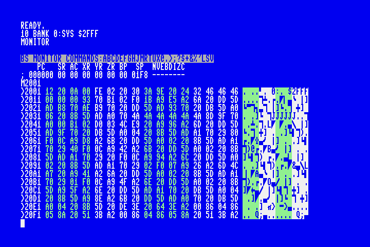
Looking at the character interpretation on the right, we can see the characters for $2FFF at the end of the first line of 16 bytes. Starting at address $2011 on the next line, we see the 00 that represents the end of the line, and the 00 00 that represents the end of the program. Our assembly language program will start at the next address, which is $2014.
The complete interpretation of these bytes is:
12 20: The memory address of the next line ($2012)0a 00: The BASIC line number ($000a=10)fe 02: The MEGA65 BASICBANKtoken20: A space character, in PETSCII30:03a::9e: TheSYStoken20: A space character24 32 46 46 46: The characters$2FFF00: Indicates the end of the line.00 00: Indicates the end of the program. If there were a second line, this would be the address of the next line.
We want ACME assembler to put all of these bytes starting at address $2001, substituting $2014 for our placeholder $2FFF, followed by the machine code for our assembly program. Everything that follows will be an assembly language program, starting with the first instruction.
Here’s a complete MEGA65 assembly language program that changes the border color, then exits:
!cpu m65
!to "hello.prg", cbm

* = $2001

!8 $12,$20,$0a,$00,$fe,$02,$20,$30,$3a,$9e,$20
!pet "$2014"
!8 $00,$00,$00

    inc $d020
    rts
The !pet directive lets us specify the $2014 part of the BASIC line as text in our assembly program. We can’t do this for the entire line because BASIC is stored in tokenized form: keywords like BANK and SYS have their own codes, and are not stored as PETSCII text.
Put that in the file hello.a, then run the acme command to produce hello.prg:
acme hello.a
Testing the program
We can test this program in two ways: run it on our MEGA65, or run it on our PC using the Xemu MEGA65 emulator. I get the impression that developers of larger programs prefer to use the emulator during development, then use an actual MEGA65 (if they have one) for final testing.
To run a PRG in Xemu, right-click in its window, select “Run PRG directly,” then locate hello.prg. You can also start Xemu from the command line with a PRG file, which is handy when automating build-and-test workflows:
xmega65 -prgmode 65 -prg hello.prg -fastclock 40
Personally, I don’t use the emulator. Instead, I use a JTAG connector to connect my PC directly to my MEGA65, then use the m65 command-line tool to send the PRG and run it. I use the M65Connect app to determine the USB serial device (which seems to change every time I reboot my Mac), then quit M65Connect (to free up the device) and run the m65 command with the appropriate parameters. Here is my build-and-test command, which I set up in my editor as a build workflow:
acme hello.a && m65 -l /dev/cu.usbserial-251633006E0E1 hello.prg && m65 -l /dev/cu.usbserial-251633006E0E1 -T "run"
I find that this is just as fast and convenient as the emulator, and I prefer using the real MEGA65 keyboard and game controllers when testing programs.
The m65 command types BASIC commands into the MEGA65 to perform its tasks. Make sure that your program is not running, the MEGA65 is at a READY. prompt, and the cursor has clear space on the screen (such as by pressing Shift+Clr/Home) before running the m65 command on your PC.
If m65 can’t type its BASIC commands, it’ll get stuck on the PC side waiting for a reply that isn’t coming. Simply terminate the command (Ctrl+C), get the MEGA65 to a clean READY. prompt, and try the m65 command again.
The GoL BASIC timing code
10 BANK 0:SYS $2014 is fine for most programs, but I actually want to do something weirder. I want my BASIC runner to resemble the outer loop of the BASIC Game of Life program, something like this:
10 INPUT"{wht}{clr}DRAW A PATTERN USING SHIFT+Q THEN PRESS RETURN:";A$
15 PRINT"{home}{50 spaces}"
20 G=1
25 M=TI
30 BANK 0:SYS $20D5
35 PRINT "{home}TIME:";TI-M,"GEN:";G;"{6 spaces}"
40 G=G+1
45 GOTO 25
In theory, using the same timing code for the BASIC version and the assembly version will allow us to compare the speed of just the part that evolves the pattern.
This also has workflow advantages: I can terminate the outer loop with Run/Stop, and have complete access to the program state in memory, just like a BASIC program. Of course, sometimes a bug in the assembly code would cause the machine to hang. Because I’m cross-assembling and sending the program over JTAG, not much is lost: I just hit the reset button on the MEGA65 and keep going.
A more complex BASIC runner probably justifies the two-file strategy: keep the BASIC in one PRG and the machine code in another, and have the first one load and call the second. But I like the one-file workflow, so I’m doing it the hard way, encoding the entire BASIC timing code in my assembly header.
!cpu m65
!to "golml.prg", cbm

* = $2001

; 10 input"{wht}{clr}draw a pattern using shift+q then press return:";a$
!8 $3d,$20,$0a,$00,$85,$22,$05,$93
!pet "draw a pattern using shift+q then press return:"
!8 $22,$3b,$41,$24,$00

; 15 print"{home}{50 spaces}"
!8 $78,$20,$0f,$00,$99,$22,$13
!pet "                                                  "
!8 $22,$00

; 20 g=1
!8 $85,$20,$14,$00,$47,$b2,$31,$3a,$fe,$02,$20,$30,$00

; 25 m=ti
!8 $8e,$20,$19,$00,$4d,$b2,$54,$49,$00

; 30 bank 0:sys $20d5
!8 $9a,$20,$1e,$00,$9e,$20
!pet "$20d5"
!8 $00

; 35 print "{home}time:";ti-m,"gen:";g;"{6 spaces}"
!8 $c0,$20,$23,$00,$99,$20,$22,$13
!pet "time:"
!8 $22,$3b,$54,$49,$ab,$4d,$2c,$22
!pet "gen:"
!8 $22,$3b,$47,$3b,$22,$20,$20,$20,$20,$20,$20,$22,$00

; 40 g=g+1
!8 $ca,$20,$28,$00,$47,$b2,$47,$aa,$31,$00

; 45 goto 25
!8 $d3,$20,$2d,$00,$89,$20,$32,$35,$00
!8 $00,$00

start
    ; The GoL routine will go here.
    rts
I determined the $20d5 address of the first machine code instruction using the monitor, as before. This is an obnoxious way to do this for larger BASIC routines that might need to change later. If I were to do more with a big BASIC header like this, I’d probably automate this using petcat, which can take an ASCII version of a BASIC program and produce a PRG file. I’d have the BASIC part in a text file, and script that calls petcat to build the PRG, truncates the load address (the first two bytes of a PRG file), determines the length, and replaces the SYS address with a calculated value. The assembly code would just use the !binary directive to insert the result at the top. Then I could edit the BASIC header as much as I like, and not worry about calculating addresses.
For hand-coding the bytes like this, two improvements could make this easier. Each BASIC line starts with a two-byte pointer to the start of the next line. The assembler knows all the addresses, so we can use labels and generate these bytes, and remove the hard-coded values:
basicline10
; 10 input"{wht}{clr}draw a pattern using shift+q then press return:";a$
!word basicline15
!8 $0a,$00,$85,$22,$05,$93
!pet "draw a pattern using shift+q then press return:"
!8 $22,$3b,$41,$24,$00

basicline15
; 15 print"{home}{50 spaces}"
!word basicline20
!8 $0f,$00,$99,$22,$13
!pet "                                                  "
!8 $22,$00

basicline20

...

basicline45
; 45 goto 25
!word basicend
!8 $2d,$00,$89,$20,$32,$35,$00

basicend
!8 $00,$00
The assembler knows the machine code start address as the label start. To give this to our SYS command we need this in the form of PETSCII characters. We can use assembly math on the address to extract each digit and calculate a PETSCII character for that digit. I’m going to use a decimal address (no $ in BASIC) to make the PETSCII character math easier.
Replace:
!pet "$20d5"
… with:
!8 start DIV 1000 + $30
!8 start % 1000 DIV 100 + $30
!8 start % 100 DIV 10 + $30
!8 start % 10 + $30
DIV is integer division, % is modulo (remainder). $30-$39 are PETSCII for the characters 0 through 9. If there’s a risk that the BASIC starter would go over decimal address 9999, we could add a digit at the beginning, and it would just be an extraneous 0 below that address. But if your BASIC header is that big, you should probably use another strategy.
With these two changes, we can mess around with the BASIC bytes when we want to tweak the outer loop and not have to worry about getting the addresses wrong.
In fact, our start of machine code address has already changed! We removed the $ from our SYS command, so BASIC is one byte shorter: start is now $20d4. The assembler has already figured this out and has written the correct address into the BASIC program.
Each BASIC line number is represented as a two-byte word. What small change could we make to the assembly code so that each line number can appear in the code as a decimal number, such as 1000 instead of $e8, $03?
Extra challenging: PETSCII characters 0 through 9 are bytes $30 through $39. PETSCII characters A through F are $41 through $46. What is a mathematical expression for the ACME assembler that calculates the PETSCII character for a hexadecimal digit given a number between 0 and 15? How would you test it?
Setting up the line buffer selector
Let’s start by writing the routines that manage the line buffer part of the algorithm. As with the BASIC version, we’ll use two rows of 80 bytes that are either 1 for an alive cell or 0 for a dead cell. This leaves quite a few bits of those bytes unused, but it’s easy to understand and troubleshoot this way. We’ll use one more byte, also just a 0 or 1, to say which set of 80 bytes is the “current row” buffer; the other one will be the “previous row” buffer.
We tell the assmebler to set aside space in memory for these bytes, and give their addresses labels we can use in the rest of the program.
linebuf
!fill 160,0
bufsel
!fill 1,0   ; if 0, cur=linebuf, prev=linebuf+80
            ; if 1, cur=linebuf+80, prev=linebuf
At the end of each row, we will need to flip the value of bufsel between 0 and 1. Let’s make this a subroutine:
swapbuf
    lda bufsel
    eor #1
    sta bufsel
    rts
This routine, in English:
- Load the value at the address
bufselinto the accumulator. The assembler replacesbufselwith the address it calculated for the label when it encountered our!filldirective. - Exclusive-or the accumulator with the number 1.
- Store the result back to the address at
bufsel. - Return from the subroutine.
1 exclusive-or’d with 1 becomes 0, 0 exclusive-or’d with 1 becomes 1. These instructions operate on full byte values, but as long as bufsel is always either 0 or 1, the other seven bits will be 0 exclusive-or’d with 0 and stay 0.
How do we test this? We need to set bufsel, call swapbuf, then inspect the result. Let’s replace our start routine to do the first two steps:
start
    lda #0
    sta bufsel
    jsr swapbuf
    rts
lda bufsel loads a value from a memory address into the accumulator. This is known as the absolute addressing mode of the lda instruction. The assembler knows that bufsel is a symbol that represents a memory address.
lda #0 loads a value that we’ve specified in the code (the number 0) into the accumulator. This is known as the immediate mode of the lda instruction. The # tells the assembler that we want the number 0 as the value. If we omitted it, as in lda 0, this would indicate the absolute mode and attempt to load whatever value is stored at memory address 0.
Let’s assemble this and send it to our MEGA65: acme golml.a && m65 -l ... golml.prg We could use our fancy BASIC runner for this, which calls the routine repeatedly in a loop. In this case, we just need to run it once. We can call it ourselves at the READY. prompt using the machine code start address we determined earlier:
BANK 0:SYS $20D4
Did it work? If it did, the value at bufsel should be a 1. How do we figure out what that address is, so we can check its contents?
The assembler knows the addresses for all of the symbols, and it can tell us! Run acme again, this time with a --symbollist file option:
acme --symbollist golml.lst golml.a
In addition to assembling the program, this creates a file named golml.lst with all of the symbol definitions in it. Open this file in a text editor to find the address of bufsel. With the enhanced BASIC header, it should be $2186.
Now we can just use PEEK() on the MEGA65 to see what’s in this memory location:
READY.
?PEEK($2186)
 1

READY.
Great! We should also check that swapbuf turns a 1 into a 0. That’s easy enough: just update the test code to lda #1 then repeat the procedure.
Resetting the line buffer
We told ACME to fill the line buffer and buffer select memory locations with 0. After our program has done an iteration of the screen, the buffer may no longer be all zeroes, and we want each iteration to start with an empty buffer. We need a routine to clear the buffer.
Here’s a terrible way to do it:
clrbuf
    lda #0
    sta linebuf
    sta linebuf+1
    sta linebuf+2
    sta linebuf+3
    ; ...
    sta linebuf+159
Both the starting address of linebuf and the size of the buffer (160) are known to the assembler, so we could just have the assembler generate 160 store instructions. If either the start address or the size were not fixed, we wouldn’t be able to do this. It’s also just a lousy waste of code. It’s a computer, we should be able to get it to count to 160.
How do we get the CPU to do something 160 times? Here’s one way:
- Set the CPU’s Y register to 160.
- Do the thing.
- Decrease Y by 1.
- Test whether Y is 0. If it’s not 0, go back to step 2.
In assembly language, this looks something like this:
    ldy #160
loop
    ; Do the thing...
    dey
    bne loop
Why are we counting down from 160 to 0, and not up from 0 to 160? We could, but it takes more code—and therefore more time—to compare Y with a specific value than to just test whether dey set it to 0. The CPU is always watching for when a register gets set to 0, and makes instructions like bne (branch if not zero) fast and easy.
We want to set each of the 160 memory locations in the line buffer to 0. There is a mode of the sta instruction that uses the Y register as an offset to determine where to store a value. Let’s try using that with our Y register countdown. Let’s also reset bufsel to 0 as part of this operation, at the end.
clrbuf
    lda #0
    ldy #160
-   sta linebuf-1,y
    dey
    bne -
    sta bufsel
    rts
We have to be a little careful here to subtract 1 from the linebuf symbol value, because Y is actually a value between 1 and 160, not 0 and 159. The assembler generates an instruction that uses the address just before linebuf as the base address, so the result is to store #0 in all of the actual linebuf locations.
We could use linebuf and not linebuf-1 as the base address by changing the order of the instructions so that Y is between 0 and 159. How would you do this?
Because it’s counting down from 160, it’s writing zeroes starting at the end of the buffer and working backwards. That’s OK! We don’t care about the order in this case, only that each location is set to 0.
I replaced the loop symbol with a - sign. This is an ACME feature that says, when bne - is encountered, look up to find the closest - label and use that as the location. This is especially useful for short loops like this, because it means we don’t need to come up with a unique symbol name for every loop in the program. You can also use + if the location is further down, and you can use symbols like -- and ++ in more complex cases where there are inner and outer loops. (ACME also supports “local symbols” if you want to give these names that can be reused elsewhere, which is a good idea if it’s not obvious what - and + mean in your code. See the ACME documentation.)
sta linebuf-1,y is the absolute Y-indexed mode of the sta instruction. It uses one more CPU cycle than absolute mode to perform its indexing feature. See this table for the cycle timings of the various sta addressing modes.
Remember that the linebuf-1 expression is calculated by the assembler, not the CPU. The CPU only does the indexing part from the address provided by the assembler.
To test this, we could write a new test routine that sets various locations in the buffer to 1, sets bufsel, then calls clrbuf. Instead of PEEK, we can use the monitor (the MONITOR command) to see the entire buffer all at once and confirm that it’s all zeroes.
- What assembly language code would you write to set various locations of
linebufto 1 then callclrbuf? - How would you determine the memory address of
linebuffor inspection in the montior? - How would you view the memory starting at this address using the monitor?
- How would you confirm that your test code is successfully setting buffer locations to 1 prior to calling
clrbuf? (If the test code isn’t working, thenclrbufmight not be working either, even though you’re seeing zeroes in the monitor.)
Setting a cell in the current row buffer
The GoL routine sets values in the current row buffer as it evaluates a row. This operation uses bufsel to determine which half of linebuf is the current row, then sets a value in that row. We said that when bufsel is 1, the first half of linebuf is the current row, otherwise it’s the second half.
This is the first subroutine we’re writing that needs parameters: the calling code specifies the column of the current row buffer and the value to write at that location. It’s only two numbers, so we can use registers for this. Let’s say the Y register holds the column and the A register holds the value, so we can use sta in absolute Y-indexed mode to store it.
setcurbuf
    ; y=column, a=value
    ldx bufsel
    bne +
    ; bufsel=0 -> curbuf = linebuf
    sta linebuf,y
    bra ++
+   ; bufself=1 -> curbuf = linebuf+80
    sta linebuf+80,y
++  rts
The calling code would set the Y and A registers prior to calling the subroutine, like so:
    ldy #7
    lda #1
    jsr setcurbuf
bra is a relative unconditional branch instruction introduced by the 65CE02. If you’re used to 6502 programming on a machine like the Commodore 64, you’d use jmp instead. bra is an improvement (faster, smaller) when jumping fewer than 128 bytes away. If ACME notices that bra is trying to jump too far, it’ll report an error.
Counting buffered neighbors
The other thing our program does with the line buffer is count the alive cells above and to the left of the current cell, stored in the previous-row and current-row buffers. (As you may recall, it’ll count the right and lower neighbors directly off of the screen, which we’ll implement later.)
This subroutine will use the Y register for the column input parameter, as we did with setcurbuf. This subroutine returns a value to the caller. We’ll use registers again, this time promising that the A register will contain the count when the subroutine returns.
In a C program, I might implement this by calculating the current row starting address and the previous row starting address from bufsel, then access the buffer locations using column offsets. My first assembly version did this, but looking back on it now, I realize that I’m probably better off breaking a cardinal rule of programming—Don’t Repeat Yourself—and just have two versions of the counting code, one for each bufsel mode, similar to how setcurbuf works. Let’s do that instead.
countbufneighbors
    ; y=column of current cel, >=1
    ; sets a to count of nw,n,ne,w neighbors
    lda #0
    clc
    ldx bufsel
    bne +
    ; bufsel=0 -> curbuf = linebuf, prevbuf = linebuf+80
    dey
    adc linebuf+80,y
    adc linebuf,y
    iny
    adc linebuf+80,y
    iny
    adc linebuf+80,y
    bra ++
+   ; bufsel=1 -> curbuf = linebuf+80, prevbuf = linebuf
    dey
    adc linebuf,y
    adc linebuf+80,y
    iny
    adc linebuf,y
    iny
    adc linebuf,y
++  rts
When using adc (add to accumulator) or sbc (subtract from accumulator), be sure to manage the carry status flag correctly. In nearly all cases, you want to clear the carry bit (clc) before you adc, and you want to set the carry bit (sec) before you sbc.
I spent hours debugging countbufneighbors because it was returning one count too many, but only when called from certain places in my code. The cause was the carry bit was set by some unrelated operation in those places, and I was not clearing the carry bit before adding the counts, so the carry bit was included in the final total. The clc instruction fixed the problem.
I only clc once in this routine because I know, in this controlled environment, that none of the adc operations will set the carry bit (the count will never exceed 255) and none of the other operations affect this bit. Refer to the instruction reference to see which operations affect which flags.
Invoking the monitor from test code
We can test countbufneighbors by setting values in the buffer, calling the routine, and making the accumulator available for inspection. Using the methods we’ve covered so far, this probably involves storing the accumulator into memory, so it can sit there safely while we exit to BASIC and type in a ?PEEK() command. The monitor can display the contents of the accumulator, but if we let the program exit to BASIC, kernel routines will overwrite the accumulator before we can inspect it.
What if we could invoke the monitor directly from our program, immediately after setting the accumulator before any other code has a chance to change it? We can, using the brk instruction. This triggers a CPU interrupt that causes the MEGA65 to invoke the monitor. The CPU preserves its state as part of this process so that the monitor can see what it looked like just before the interrupt.
Here is code to set the west, north, and northeast neighbors of cell #6 on the current row. It uses setcurbuf and swapbuf to update the line buffers. It then asks countbufneighbors to report on cell #6. If everything is working, the accumulator should contain 3, and when we brk, the monitor will report this.
start
    ldy #5
    lda #1
    jsr setcurbuf
    jsr swapbuf
    ldy #5
    lda #0
    jsr setcurbuf
    ldy #6
    lda #1
    jsr setcurbuf
    ldy #7
    lda #1
    jsr setcurbuf
    jsr swapbuf
    ldy #6
    jsr countbufneighbors
    brk
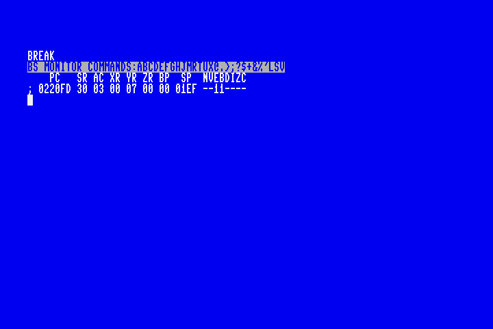
When you’re done using the monitor, you can exit to BASIC by entering the command X. However, if you are using M65Connect or m65 to transfer your PRG to MEGA65 memory, there is currently a bug where the transfer process breaks the X monitor command. As a workaround, reset your MEGA65, and re-send the PRG as needed.
Another way to exit the monitor is to resume the interrupted program. To do this, use the G command. See Using the MEGA65 Monitor to troubleshoot assembly programs for more information about the monitor.
Writing test results to the screen
So that’s two ways of inspecting the accumulator: writing the accumulator to memory and exiting to BASIC to inspecting that memory, or using brk to invoke the monitor and view the accumulator directly. It would be convenient if we could just display the value of the accumulator on the screen from the program, especially if we want to run multiple tests.
It is possible to call MEGA65 kernel routines to print numbers on the screen, but for simple cases I find it’s easier to store the accumulator directly into screen memory. It appears as the screen code for the value, and not a number, but for small numbers it’s easy to interpret the symbol.
You may recall from the BASIC GoL program that screen memory begins at address $0800 for the upper left corner, and increases left then down. On an 80 character screen, that puts the leftmost column two rows down at address $08a0. Let’s try writing the accumulator there.
Remove the brk instruction, then add:
    sta $08a0
    rts
This puts a C on the screen at that location. The screen code for C is 3, so our test is working as expected. @ is 0, and the numbers 1-26 are the letters A through Z. For larger values, another method may be worth the investment (so you don’t have to keep referring to a screen code reference chart), but this is plenty for now.
Using macros for test code
Our countbufneighbors test involves quite a few instructions. It’d be a good idea to test multiple combinations of neighbors and see the results, and it’d be cumbersome to change and run the code separately for each combination.
One possible improvement would be to put the test code in a subroutine that takes parameters on registers, similar to our other subroutines. Then we can test each combination of neighbors by setting up calls to the subroutine, one per combo. The MEGA65 only supports four registers, which limits our ability to describe test cases. We could reserve a region of memory for test parameters, or use the stack like a C compiler might for functions with many parameters. This is a lot of code just to run some tests.
There’s another option worth considering: macros. Macros tell the assembler to generate a bunch of code according to a template. Macros accept parameters that can guide what code is generated for each call to the macro. They are easy to write, and easy to use. As long as you don’t mind that the assembler regenerates the code each time they’re invoked in the source, they can be a powerful way to express intent and manage complexity.
Let’s rewrite our countbufneighbors test as a macro:
!macro test_countbufneighbors .num, .w, .nw, .n, .ne {
    ldy #5
    lda #.w
    jsr setcurbuf
    jsr swapbuf
    ldy #5
    lda #.nw
    jsr setcurbuf
    ldy #6
    lda #.n
    jsr setcurbuf
    ldy #7
    lda #.ne
    jsr setcurbuf
    jsr swapbuf
    ldy #6
    jsr countbufneighbors
    sta $08A0+.num
}

start
    +test_countbufneighbors 0, 1, 0, 1, 1
    rts
This macro accepts five parameters: a test number, and values for the west, northwest, north, and northeast neighbors. It sets those values in the line buffers around cell #6, calls countbufneighbors, then displays the result on the screen, using the test number to find a screen position.
The +test_countbufneighbors line tells the assembler to generate all of the same code as before. We can use the macro more than once to define multiple test cases. The assembler generates a new set of instructions for each test case according to the parameters.
start
    +test_countbufneighbors 0, 1, 0, 1, 1
    +test_countbufneighbors 1, 0, 0, 0, 0
    +test_countbufneighbors 2, 0, 0, 0, 1
    +test_countbufneighbors 3, 0, 0, 1, 1
    +test_countbufneighbors 4, 0, 1, 1, 1
    +test_countbufneighbors 5, 1, 1, 1, 1
    +test_countbufneighbors 6, 1, 1, 1, 0
    +test_countbufneighbors 7, 1, 1, 0, 0
    +test_countbufneighbors 8, 1, 0, 0, 0
    rts
If everything is working, these tests cases print C@ABCDCBA. Take a moment to confirm that this is the expected result.
Macro parameters begin with a ., such as .num. This indicates that the symbol is local to the scope of the macro, and won’t conflict with other symbols of the same name used elsewhere in the code. You can define scopes (which ACME calls “zones”) for local symbols elsewhere in your code. See the ACME documentation for the !zone directive.
Our strategy for traversing the screen
Our GoL update routine visits every cell on the game board, starting from the top-left corner, moving left then down. As with the BASIC version, we enforce a one-character border around the game board, so the traversal is not a straight walk through all of the screen memory addresses. We’ll need to count rows and columns as we go.
We’ll be doing a lot of work at each location on the game board, so we can’t keep our indicies in registers. Let’s set up memory locations for the row counter and column counter:
row_ct
!fill 1,0
col_ct
!fill 1,0
We will maintain a pointer (a memory location that contains an address) to the screen memory location of the current cell. We will increment this by 1 for each column, and by 3 at the end of each row to skip the side borders.
We’re going to do something special with the cell pointer. Instead of setting aside a regular location in program memory, we will use memory locations $00fb and $00fc. These will store a 16-bit memory address stored least-significant-byte first. For example, when the cell pointer is in the top-left corner of the game board, that screen memory location is $0851, so we store $51 in $00fb and $08 in $00fc.
Base page indexing
The locations $00fb and $00fc are in the first 256 bytes of the computer’s memory. In 6502 parlance, this area is known as the zero page. The 6502 line of processors gives the zero page special treatment. Instructions have special addressing modes for the zero page that are faster and smaller than other modes. Some instructions can use an address stored in the zero page as the base address for an indexed operation, known as zero page indexing. We’ll be using this feature to read neighbor cells out of screen memory.
The zero page is so useful that nearly every address in it gets used by the kernel and BASIC environment. The Commodore 64 leaves a few addresses unused, so machine code that wants to work with BASIC still has a few bytes to play with. $fb-$fc are bytes left unused by the C64 BASIC. MEGA65 BASIC reserves all 256 zero page bytes. I haven’t had issues borrowing $fb-$fc directly from the zero page in this case, but it is not guaranteed to work when we return control to BASIC.
A better practice is to take advantage of a feature introduced with the 65CE02 CPU: you can pick another page in memory to be the zero page, better known as the base page because it doesn’t have to be zero. The location of the base page is set in an 8-bit register known as B, equal to the first two digits of the 16-bit address. The CPU sets B to $00 when it turns on so it behaves like a 6502 by default. You can change it by loading the page number in the accumulator, then calling the tab instruction (transfer A to B). Pages $16 and $17 are unused by MEGA65 BASIC. If you’re not using BASIC graphics routines you could also use $18-$1f.
Let’s define a symbol for the cell pointer in the zero page, so we can refer to it by name. We use $fb and not $00fb to make sure ACME knows we’re trying to use the base page addressing modes of the instructions that refer to it.
cell_ptr = $fb
In the start routine, we initialize the cell pointer and counters. While we’re here, let’s make sure the MEGA65 is running in 40 MHz mode, switch the base page, and clear our line buffers:
start
    ; Make sure we're running at 40 MHz
    lda #65
    sta $00

    ; Use base page $16
    lda #$16
    tab

    ; Reset the row buffer
    jsr clrbuf

    ; Traverse playable region of screen
    ; Start at $0851
    ; For 23 rows: add one 78 times; then add three
    lda #$51
    sta cell_ptr
    lda #$08
    sta cell_ptr+1
    lda #23
    sta row_ct
    lda #78
    sta col_ct
We need to switch the base page back to 0 before returning to BASIC. The start routine will end like this:
    ; Switch back to base page 0.
    lda #$00
    tab

    rts
In the case of our GoL program, all of the program memory we’re reserving for the line buffers and variables could fit in the base page, assuming we switch to page $16. We would just need to choose addresses and replace our row_ct !fill 1,0 directives with assignments like row_ct = $a1. I’ve opted not to do this here, but give it a try!
The traversal loop
With row_ct and col_ct initialized and cell_ptr in the starting position, the traversal logic looks like this. We’ll fill in the “Cell logic goes here” in the following sections.
next_col

    ; *** Cell logic goes here ***

    ; advance cell_ptr to next cell
    dec col_ct
    beq last_col
    clc
    lda #1
    adc cell_ptr
    sta cell_ptr
    lda #0
    adc cell_ptr+1
    sta cell_ptr+1
    bra next_col
last_col
    ; swap row buffers
    jsr swapbuf

    ; reset col_ct, advance to next row
    lda #78
    sta col_ct
    dec row_ct
    beq last_row
    clc
    lda #3
    adc cell_ptr
    sta cell_ptr
    lda #0
    adc cell_ptr+1
    sta cell_ptr+1
    jmp next_col
last_row
As with other loops we’ve seen, we’re counting downward to zero for both the column counter and the row counter. For each column we add 1 to cell_ptr, then loop back to next_col. When the column counter hits zero, we jump to last_col for end-of-row logic. At the end of the row, we swap the line buffers, reset the column counter to 78, add 3 to cell_ptr, then loop back to next_col. When the row counter reaches 0, we’re done (last_row).
Because cell_ptr is a 16-bit value stored over two memory locations, we need to perform our addition in a way that carries overflow from the lower byte to the higher byte, similar to how you would carry a 1 in decimal addition when two digits add up to more than 10. This is where that pesky carry bit comes in: if adc cell_ptr causes the lower byte to go over 255, the CPU sets the carry bit. When we adc cell_ptr+1, that carry bit gets included in the total.
The complete process for adding the 16-bit constant $0003 to the 16-bit value stored at cell_ptr:
- Clear the carry bit:
clc - Load the low byte of the first term into the accumulator:
lda #3 - Add-with-carry the low byte of the second term to the accumulator, potentially setting the carry bit:
adc cell_ptr - Store the new low byte:
sta cell_ptr - Load the high byte of the first term into the accumulator:
lda #0 - Add-with-carry the high byte of the second term to the accumulator:
adc cell_ptr+1 - Store the new high byte:
sta cell_ptr+1
Altogether, this starts cell_ptr in the top-left corner of the board, then visits every cell from left to right, top to bottom, leaving a one-character border around the screen untouched. Now we just need to do something with each cell.
Storing the current cell in the current row buffer
We’re nearly done! We have three things to do at each cell, which we’ll put where “Cell logic goes here” appears above.
First, let’s get the value of the current cell off of the screen, and store it in the current row buffer. As with the BASIC version, we want to treat a filled circle as an alive cell and any other character as a dead cell.
    ; set the current cell value in the current row buffer
    ldy #0
    lda (cell_ptr),y
    cmp #$51
    beq +
    ldx #0
    bra ++
+   ldx #1
++  sec
    lda #79     ; 79-(col_ct) = screen col number
    sbc col_ct
    tay    ; y = column
    txa    ; a = 1 if set, 0 if not
    jsr setcurbuf  ; uses y and a
To load the value of screen memory pointed to by cell_ptr, we use the zero page indirect indexing mode of lda. As shown here, this mode requires the use of the Y register as an offset. We don’t need an offset here, so we set Y to 0.
With the screen code in the accumulator, we compare it to #$51, the screen code for the filled circle. If it’s a match, we set the X register to 1, otherwise 0. We’re using the X register because we need the accumulator free for the next step.
Our setcurbuf routine expects a column number from 0 to 79, left to right from the screen edge. col_ct is a countdown from 78 to 0. To convert this to a screen column coordinate, we subtract col_ct from 79. (Take a moment to confirm this is correct.) You must set the carry flag (sec) before starting a subtraction with sbc to indicate that a previous subtraction did not borrow a 1 from this column.
Similar to adc, you can subtract multi-byte values from least significant to most significant byte. The carry flag remembers whether a subtraction borrowed a 1. See The 6502 Overflow Flag Explained for a complete explanation.
setcurbuf wants the column coordinate in the Y register, so we transfer it from the accumulator (tay). It wants the 0/1 value of the cell in the accumulator, so we transfer it from the X register (tax). Now we can call setcurbuf.
Counting neighbors
We need to count all of the neighbors of the cell. We have a routine to count four of the eight neighbors from the line buffers. We’ll need to add to this count. Let’s store the complete count in a new memory location. Put this with the others:
neighbor_ct
!fill 1,0
Back in the cell processing code, we call our countbufneighbors routine to count the northwest, north, northeast, and west neighbors. This routine expects the column coordinate in the Y register, and it’s still there from our call to setcurbuf (because setcurbuf does not change the Y register), so we can just go straight to the routine. We store the result in neighbor_ct.
    ; count buffer neighbors
    jsr countbufneighbors  ; y = column; sets a to count
    sta neighbor_ct
Now we just need to read the east, southwest, south, and southeast neighbors directly out of screen memory.
    ; count screen neighbors (east, southwest, south, southeast)
    ldy #1
    lda (cell_ptr),y
    cmp #$51
    bne +
    inc neighbor_ct
+   ldy #79
    lda (cell_ptr),y
    cmp #$51
    bne +
    inc neighbor_ct
+   iny
    lda (cell_ptr),y
    cmp #$51
    bne +
    inc neighbor_ct
+   iny
    lda (cell_ptr),y
    cmp #$51
    bne +
    inc neighbor_ct
+   lda neighbor_ct
Again, $51 is alive and anything else is dead, so we use cmp instructions and branches for each one. When we find an alive neighbor, we inc neighbor_ct, a single instruction that increments a memory location. Zero page indirect indexing allows us to find neighbors in screen memory simply using offsets via the Y register: +1 is the neighbor directly to the east, and +79 is one short of a full line down for the southwest neighbor. We increment Y (iny) for the last two because it’s faster than setting Y to 80 and 81.
We load the neighbor_ct back into the accumulator for the last step.
Determining the fate of the cell
The last thing to do is apply the rules of Life and update the cell on the screen.
    ; update cell according to neighbor rules
    ldy #0
    cmp #3
    beq +
    cmp #2
    bne ++
    lda (cell_ptr),y
    cmp #$51
    bne ++
+   lda #$51
    bra +
++  lda #$20
+   sta (cell_ptr),y
This is a clever paraphrase of the rules to keep the assembly code concise. In English:
- If the cell has three neighbors, it is alive in the next generation, regardless of its previous state.
- If the cell does not have two neighbors, it is dead in the next generation, regardless of its previous state.
- Check to see if the cell was alive in the previous generation, i.e. if there’s a filled circle already at this screen location. If not, it is dead in the next generation. Otherwise it is alive.
This code uses the + relative label twice. Remember how this works: when used, it refers to the first + label it finds further down. The second + label on the last line is only used by the bra + statement just above it.
Running the program
Whew! We’re done! Let’s see how it compares to the BASIC version.
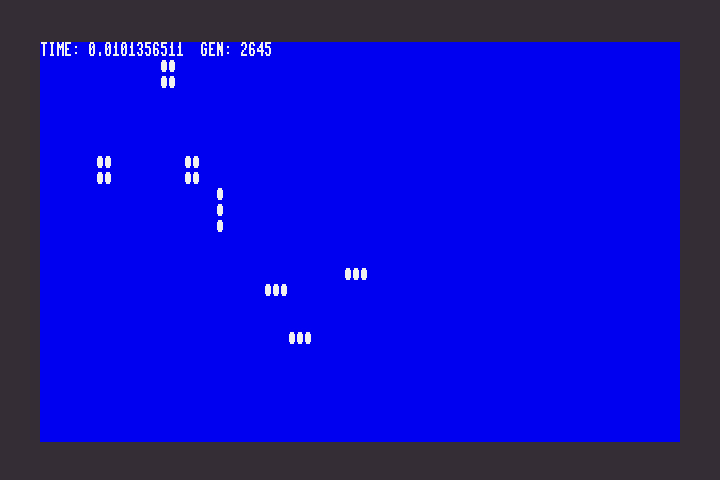
As we had hoped, this program runs identically to the BASIC version: it uses a BASIC INPUT statement to allow the user to draw a pattern with filled circles, then when they press Return, it starts evolving the pattern.
There’s just one difference in the new version. It’s extremely fast.
The BASIC version clocked in at 3.04 seconds per generation. According to identical timing code, the assembly language version clocks in at 0.01 seconds per generation—or 100 generations per second.
Because the outer loop is in BASIC, you can stop the execution of the program by pressing Run/Stop.
More debugging techniques
It’s easy enough for me to present a known-working program one piece at a time and pretend it’s a tutorial. The actual process of getting this working was a little more involved.
We discussed writing values to screen memory for inspection purposes. On multiple occasions, I found it useful to disable the routine that updates the screen (usually just by commenting it out) and instead replace each cell with its neighbor count (ldy #0, lda neighbor_ct, sta (cell_ptr),y). This gave me a crude visual representation of the neighbor count field that I could use to troubleshoot the different pieces of the neighbor counting routines.
I often wanted the machine code to pause while I stared at the screen in puzzlement. To do this, I used this subroutine that waits for a key press:
!addr UART_ASCIIKEY = $D610
debug_waitkey
    lda UART_ASCIIKEY
    beq debug_waitkey
    sta UART_ASCIIKEY
    rts
This mostly works, but in the case of this specific program, the first few calls to debug_waitkey after answering the “draw a pattern” prompt tend return right away, probably having just seen me type Return and whatnot. I worked around this by calling debug_waitkey multiple times at the top of the program when a pause was needed later on.
Sometimes I just needed to see that a line of code was reached—especially in a series of calls to debug_waitkey that might otherwise not show anything on screen. I reached for the ultimate classic technique, incrementing the border color: inc $d020. Sometimes I needed two indicators, so I used the background color as well: inc $d021. Of course, any screen location would also work for this, so I could watch a bunch of “got here” indicators change their screen codes.
I mentioned using brk to drop into the monitor. On the MEGA65, another way to reach a monitor is the Freezer menu: hold Restore, then release to freeze the system state and bring up the menu, then select M to start a monitor. For some reason, it’s not the same monitor as the one that starts by brk or the MONITOR command. But it works well enough for inspecting memory, and has the advantage of being able to restore the frozen execution state. The main disadvantage is you have to use a keypress to activate it, so you can’t control exactly where in the code it freezes.
Next steps
I wonder how much of the 0.01 seconds is the overhead of the BASIC timing code. I would be curious to port the outer loop and timing display to assembly language to speed it up further. It’d only account for the few lines that subtract and print the time, so it might not be a huge increase.
I’d be curious to try moving the line buffer and all variables to the base page to see if that runs ever so slightly faster.
Of course, we could make this into a full-fledged application, with an easier-to-use pattern editor, a built-in pattern library, loading and saving, stepping and speed controls.
It’d fun to use bitmap graphics for higher resolution patterns and a larger game board. Generations would be slower but it might still be fast enough to be usable for exploring large patterns. MEGA65’s capabilities include double-buffering and hardware-based direct memory access techniques for smoother animation. Could the evolution routine itself be hardware accelerated?
Try it!
Have any ideas for improvements, alternate methods, or debugging advice? Appalled by my naïve coding style and lack of technique? Let me know!
To play with this code yourself:
- golml.a : The assembly language program for ACME assembler
- To build the PRG:
acme golml.a
- To build the PRG:
- golml.prg : The assembled PRG file, ready to run