KERNAL of Truth
KERNAL of Truth. Dan’s MEGA65 Digest for June 2024.
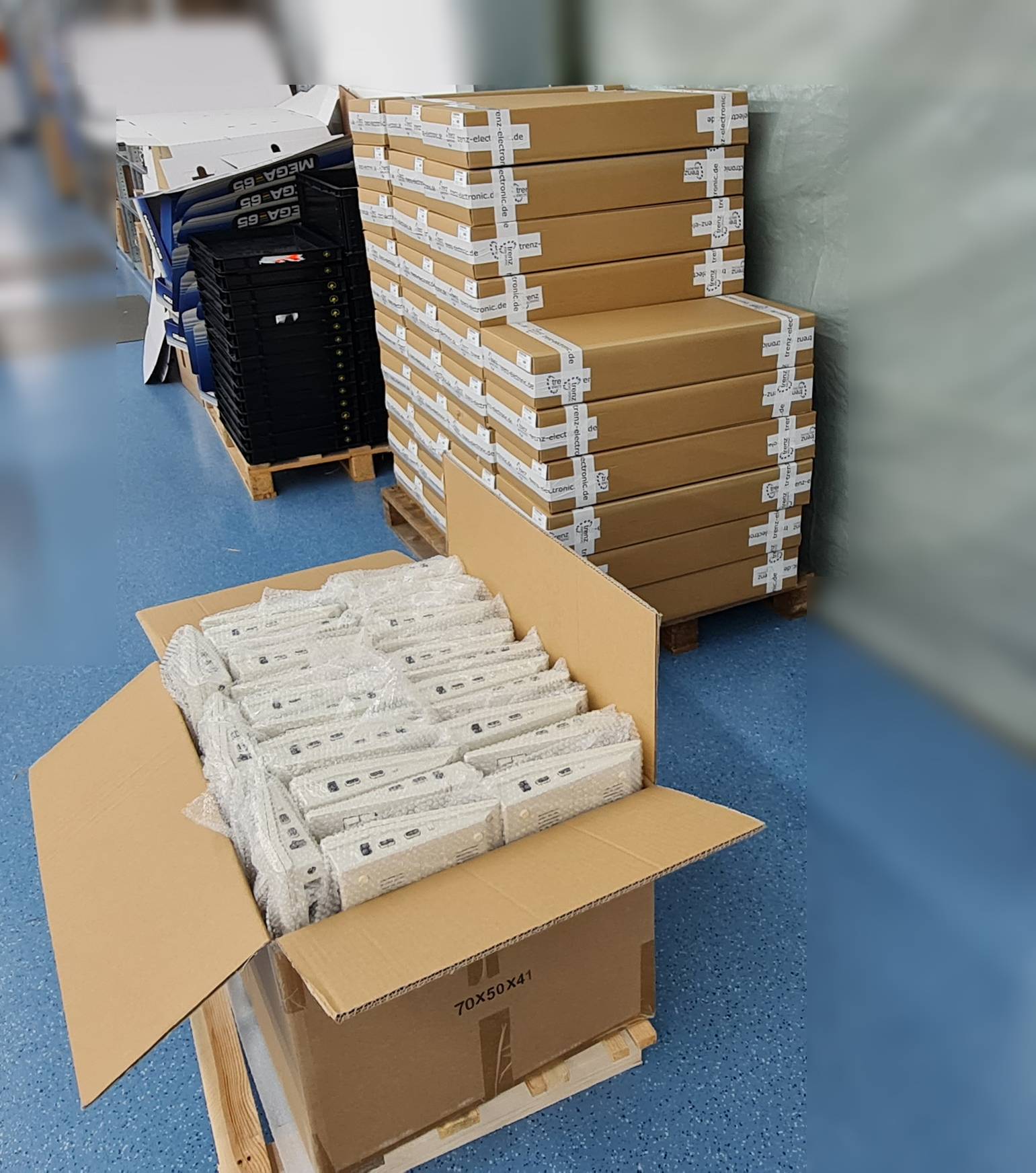
The Summer of MEGA65 begins! The latest delivery batch is in progress, and many preorder holders are receiving their new favorite computer.
If you’re new to this Digest, welcome! Here you’ll find news about the MEGA65 and community projects, and interactive feature articles of things you can try for yourself. Read the Digest while next to your MEGA65 and PC for the best experience.
Also, every Digest has a read-aloud audio edition. Click the audio player at the top of the email or website, or subscribe to “Dan’s MEGA65 Digest” in your podcast player. I don’t know how many people listen to it, but I enjoy making it.
In this Digest, we’ll start taking a look at the MEGA65 KERNAL, the main operating system of the computer. We’ll build off of last month’s discussion of interrupts and the CPU memory map, and try writing a MEGA65 version of a classic KERNAL extension: a desktop time-of-day clock.
Let’s get started!
Batch #3 is arriving!
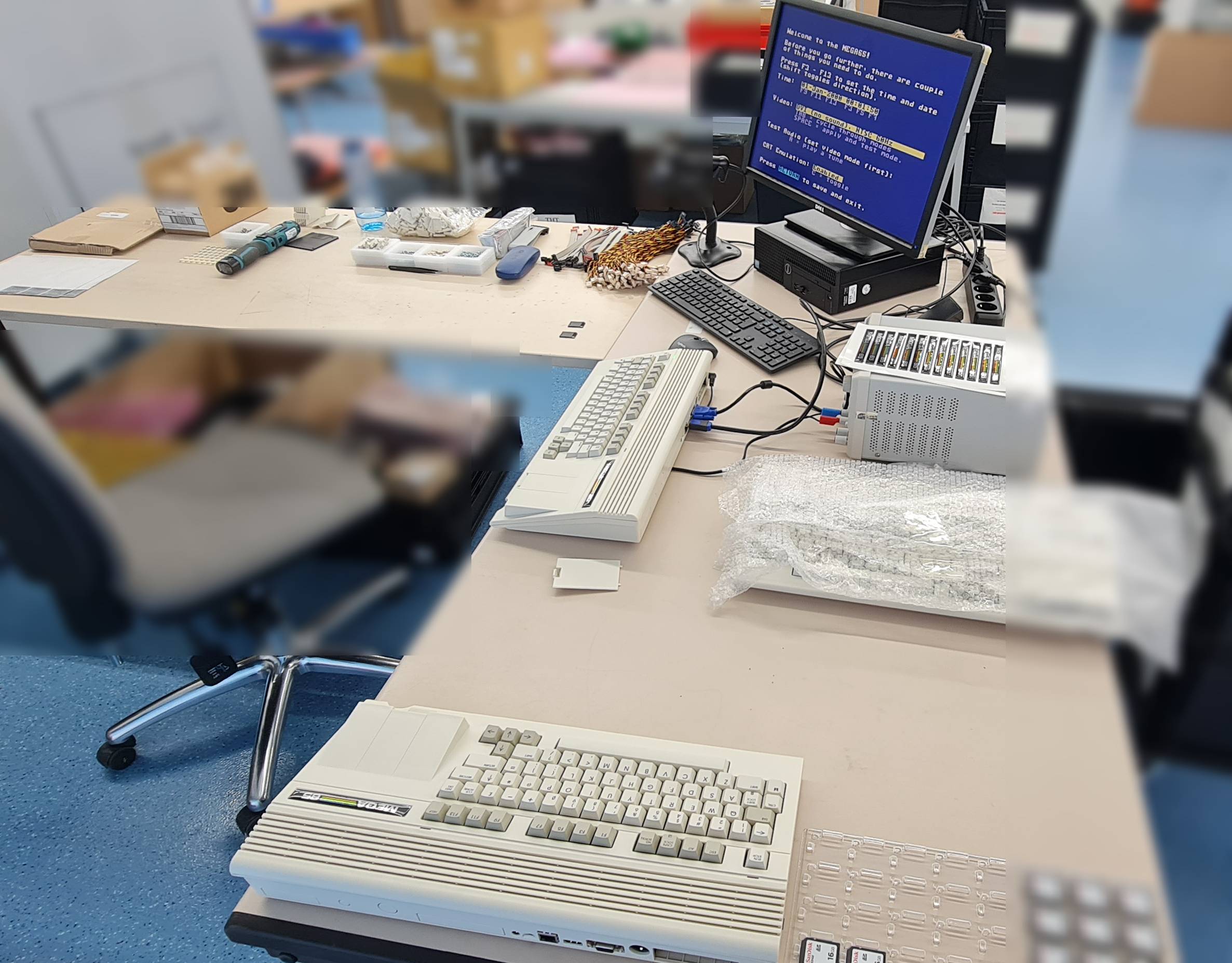
MEGA65s being tested, courtesy Trenz Electronic
MEGA65 home computers are now arriving with their new owners! Trenz Electronic has begun sending out the third manufacturing batch, and will continue to fulfill pre-orders steadily. Congrats and welcome to everyone receiving a new bundle of joy!
Back in January, we were able to confirm with Trenz that this manufacturing batch will be large enough to cover all preorders placed up to that point. I continue to use that as a conservative estimate. New preorders placed in the last few months may need to wait a bit longer—or maybe not. For all we know, Trenz may be able to make quick work of another batch and get everyone taken care of. Rest assured that everyone involved in this project wants you to have a MEGA65 as soon as possible.
Of course, you can still order the MEGA65 if you haven’t already. Tell your friends!
MEGA65 at the Pacific Commodore Expo Northwest, June 22-23, 2024

Pacific Commodore Expo Northwest.
If you’re near Seattle, Washington, USA this month, I will be presenting the MEGA65 at the Pacific Commodore Expo Northwest, June 22-23, 2024. Admission is free. The space is cozy and filled with Commodores, and this year we have access to additional space for presentations. I’ll have my MEGA65 at a table all weekend for people to try.
I gave a talk on the MEGA65 at last year’s PaCommEx NW that went reasonably well, despite being hastily planned. Here’s hoping that I’ll have this year’s talk figured out in time. 😬
The Silent Enigma

The Silent Enigma, by Gurce
The Silent Enigma is a new demo by Gurce, based on the song by Anathema. Gurce wrote the demo in BASIC 65 with the Eleven IDE, with assembly language helper routines in Mega Assembler and Acme, and an extended version of grim-fandango’s MEGAPLOT library.
The current version of the demo requires customized versions of the MEGA65 core and ROM to run on MEGA65 hardware. Gurce discovered a need for a new feature of the KERNAL for combining BASIC and machine code routines, and also discovered a core bug while getting it to work. We’re working on getting these improvements into the core platform. In the meantime, Gurce is distributing modified core and ROM files with the demo.
Check out retroComb’s video debuting The Silent Enigma, along with an interview with Gurce. And don’t miss the Eleven and assembly language source files included on the disk!
Lala The Magical (preview)

Lala the Magical (preview) for the MEGA65, by Majikeyric
Majikeyric is previewing a new game for the MEGA65! Lala the Magical (preview) is an adorable puzzle platformer, with parallax scrolling areas and tons of enemies and collectibles. It’s based on the PC DOS game by the Mojon Twins.
In the ancient ruins (province of Badajoz) lives Lala with her teacher. She is learning magic but still has a long way to go.
“Tell me about the Sky Palace” – asks Lala, and her teacher tells her again about the three Power Gems hidden inside. “I’d love to see them”, but Lala’s teacher would say no… “It’s too dangerous, and powerful magic is required to traverse the palace”.
You can play the preview with a joystick. Sound, music, and polish are in progress. I’m looking forward to the final product!
Wonder Boy core

Wonder Boy, arcade core by muse
muse continues his series of arcade cores with Wonder Boy. This colorful side-runner will have you running, jumping, and even skateboarding across the landscape, collecting fruit and dodging creatures.
This core is available for both R3 (2022) and R6 (2024) MEGA65s. Be sure to use the correct version for your system, and follow the installation instructions.
Arcade cores use the MEGA65’s FPGA to fully recreate arcade game chipsets with a high degree of accuracy. Thanks to muse for his continued dedication to the arcade core library!
The role of the KERNAL
In computer architecture, the kernel is the center of a computer’s operating system. It manages access to hardware such as the keyboard, storage devices, and peripherals, as well as other common facilities. Programs—including the rest of the operating system—access these facilities by interacting with the kernel.
The Commodore KERNAL has played this role in Commodore 8-bit computers all the way back to the Commodore PET. The proper name, spelled with an “A” and all uppercase, is credited to an honest misspelling of the word “kernel” by developer Robert Russell that made its way into the VIC-20 programmer’s manual. While the KERNAL has evolved substantially across the line all the way up to the Commodore 65, its role in the computer and many of its key features and interfaces have remained largely the same since 1977.
In total, a Commodore computer’s operating system consists of the KERNAL, the BASIC interpreter, and the screen editor. The machine code for the operating system is etched into a ROM chip, wired to be the first thing the CPU sees when it wakes up. If the KERNAL detects that a C64-style cartridge is connected, it passes control to the cartridge. Otherwise, the KERNAL starts the screen editor, from which the user can load and run programs, type other commands, or start programming in BASIC. These three components tend to share some responsibilities, and the distinctions between them can be a bit blurry in some places, but that’s the general idea.
(There’s an interesting historical exception to the start-up procedure. The Commodore 64 was designed with support for cartridges made for the Commodore MAX, aka “Ultimax” or “VC-10.” An Ultimax cartridge connects directly to the 6510 chip’s I/O lines in a way that causes the CPU to go directly to the cartridge for its first instructions. The Ultimax did not have its own operating system: it relied on the connected cartridge for everything.)
Programming with the KERNAL
There are three main ways the KERNAL participates in the execution of programs: KERNAL subroutine calls, the KERNAL IRQ handler, and vectors.
KERNAL subroutines
A program can call subroutines in the KERNAL code to perform tasks and interact with the KERNAL’s systems. Here’s a simple machine code program that writes a short message to the screen by calling the KERNAL subroutine BSOUT:
bsout = $ffd2

    lda #'H'
    jsr bsout
    lda #'I'
    jsr bsout
    lda #13
    jsr bsout
The BSOUT routine writes a single character to the current output device, which by default is the screen editor. The program sets the accumulator to the character to be written as a PETSCII code, then calls BSOUT with the JSR instruction to address $FFD2. The subroutine does all of the work to write the character, then returns.
The screen editor does a lot of work here. It maintains a text cursor—the same one that you type with at the READY prompt—that has a position on the screen, and a draw state including the text color and other attributes. When it receives a character from the program via BSOUT, the screen editor figures out what changes to make to screen and character attribute memory, moves the cursor position, and scrolls the screen up if the text runs off the bottom. (Other PETSCII codes change the draw state or cursor position in other ways.)
The screen editor is a full-fledged built-in application that behaves like an input/output terminal. Your program writes to and reads from this terminal using KERNAL subroutines.
The KERNAL subroutine jump table
$FFD2 is not actually the memory location of the BSOUT subroutine. Instead, the KERNAL keeps a JMP instruction at that address that goes to the actual subroutine code. Each KERNAL subroutine available to programs has one of these, in a fixed memory location called a jump table.
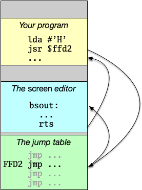
The jump table provides a critical layer of compatibility across different versions of the KERNAL. Your program needs an explicit address to where it can jump, to invoke the subroutine. When the KERNAL developers inevitably need to relocate the subroutine code to a different address in a new version of the operating system, they can just update the address in the jump table, and your program (and everyone else’s) will continue to run correctly because the jump table itself doesn’t move.
I recently added an appendix to the MEGA65 Compendium describing all of the KERNAL subroutines and how to use them, including jump table addresses, CPU register arguments, and example programs. Check it out, and let me know what you think!
The KERNAL raster IRQ
As we covered in detail in last month’s Digest, you can program the VIC video chip to tell the CPU when its raster beam is at a given vertical location on the screen. This triggers an interrupt that causes the CPU to call a special kind of subroutine known as an interrupt handler. A typical use of the vertical raster beam interrupt is to have a chunk of program code that gets called many times per second at regular intervals. This allows the program to be organized as if it is two programs running side by side: a main program that runs normally, and a short secondary program kicked along by the interrupt.
The KERNAL uses this raster interrupt in this way. It installs an interrupt handler that pays regular attention to KERNAL subsystems while the user’s program is running. The KERNAL IRQ handler drives behaviors of the screen editor such as blinking the cursor and checking for special keyboard combinations like Mega + Shift, and behaviors of BASIC such as sprite move animations (from the MOVSPR command) and music playback (from the PLAY command).
Most programs can just take for granted that the KERNAL is doing its own thing with the raster IRQ. As we saw last month, only one IRQ handler can be installed at a time, so a program that wants to take over the IRQ handler must disable the KERNAL. But the KERNAL has a way it can share its IRQ handler with a program, so they can both play…
KERNAL vectors
The KERNAL generously offers programs the ability to replace or extend some of the KERNAL’s own subroutines. In these cases, when the KERNAL wants to call one of its own subroutines, it looks up the address in a table. This table is initialized to the address of the KERNAL’s version of the subroutine, so without changes, everything behaves normally. A program can replace that address with an address of its own, so the KERNAL calls the program’s routine instead. This indirect address is called a vector, because of how it points to where the KERNAL will go.
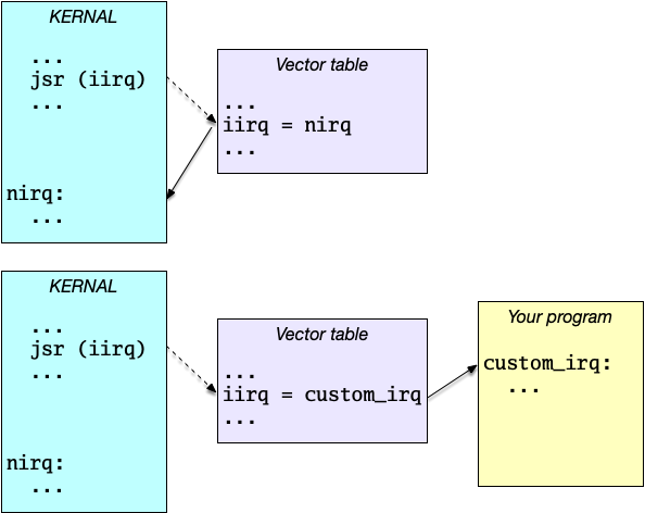
A program can replace a KERNAL routine by re-pointing a vector, but this is a heavy task in most cases. Much more common is to extend the existing KERNAL routine with additional functionality. It works like this:
- Read the address of the original KERNAL routine from the vector table.
- Write that address into a JMP instruction at the end of the program’s custom routine.
- Re-point the vector to the beginning of the custom routine.
Now when the KERNAL calls the vector, control goes to the custom routine. The custom routine does some custom things, then jumps to the KERNAL’s original routine. The KERNAL routine still does the heavy lifting, and the custom routine just adds a bit of extra functionality.
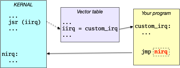
This is how the KERNAL can share its IRQ handler. In the middle of the KERNAL’s IRQ handler, it calls a vector that points right back at the rest of the IRQ handler. A program can use the vector to insert its own routine that gets called as part of the KERNAL’s raster IRQ. This way, the program can combine the KERNAL IRQ and its custom IRQ routine, all running alongside its main program code.
Custom vectors remain installed when your program returns to BASIC. This allows a program to extend KERNAL behaviors used by BASIC and the screen editor. The custom IRQ vector is especially fun for this. A game written in BASIC can invoke a small amount of machine code to install an IRQ vector that plays a SID music file, and this music plays in the background while BASIC runs the rest of the game. You could even listen to SID music while writing your BASIC program, with the playback routine running alongside the screen editor!
Note that Run/Stop + Restore will reset KERNAL vectors. There are ways to prevent this, but we won’t cover them here for now. In general, this is a good thing, so you can get the system back to normal when a bug in a vector routine gets out of control.
The VECTOR accessor
The KERNAL keeps its vector table in its own private memory location. To read from or write to the vector table, a program calls a KERNAL subroutine that copies the table to or from the program’s memory. The full procedure for installing an extension vector routine is:
- Call VECTOR, telling it to copy the vector table to program memory.
- Copy the original vector address from the table into a JMP instruction at the end of the custom routine.
- Write the address of the custom routine to the program’s copy of the vector table.
- Call VECTOR again, telling it to copy the vector table from program memory into KERNAL memory.
Some Commodore programmers are accustomed to reading and writing custom vector addresses directly from internal KERNAL memory, without using the VECTOR routine. For the MEGA65, it is important for programs to use the VECTOR accessor routine, and to not depend on the internal KERNAL memory address. Just like how the jump table protects your program from KERNAL subroutines jiggling around between ROM versions, the VECTOR accessor protects your program from the KERNAL vector table jiggling in the same way.
We’ll try an example below. See the entry for VECTOR in the “KERNAL Jump Table” appendix of the Compendium for a complete explanation, along with a description of the vector table.
A bit more about the MAP
Last month, we briefly considered the CPU memory map, just enough to understand that the KERNAL assigns itself into the $E000-$FFFF address range so it can take over the IRQ handler address stored at $FFFE-$FFFF. We ditched the KERNAL by zeroing out the memory map, so all 16-bit addresses referred to RAM in the MEGA65’s first (well, zeroth) 64K memory bank.
I will continue to avoid a complete description of the MAP register—see the “Memory” chapter of the Compendium for that—but it’s worth knowing a bit more about how the KERNAL uses MAP when integrating with it using jump table entries and vectors.
Mapping 16-bit addresses to 28-bit addresses
Recall that the CPU sees 64KB of memory at a time, using 16-bit addresses $0000 to $FFFF. The MEGA65 has a much larger 28-bit address space, $000.0000 to $FFF.FFFF. The memory map assigns 8KB regions of the 16-bit space to parts of the 28-bit space, and a program can reconfigure this map with the CPU instructions map and eom.
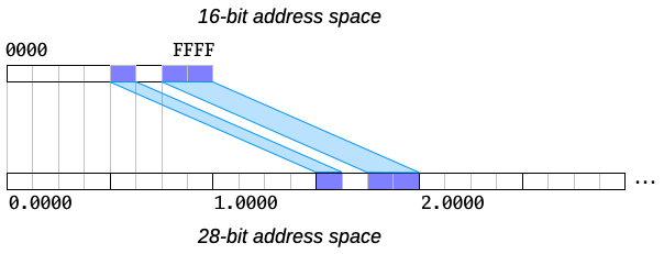
There are actually a few ways the CPU can read and write memory using full 28-bit addresses without changing the map. Crucially, the CPU can only execute machine code instructions via 16-bit addresses. In other words, to execute code somewhere in the MEGA65’s memory, the memory map must have an 8KB region mapped to that location. Instructions like JMP use the 16-bit address into the memory map to find that code.
Two KERNAL maps
When the MEGA65 starts, it runs BASIC, the screen editor, and the KERNAL all together to power the familiar READY prompt, blinking cursor, program line editor, and library of BASIC commands. The operating system code that powers all of this lives in bank 3. There’s a lot of it, so in this mode, most of the memory map points to bank 3. Specifically, $2000 to $BFFF refer to $3.2000 to $3.BFFF, and $E000 to $FFFF refer to $3.E000 to $3.FFFF.

If the operating system is hogging most of the 16-bit addresses, where does our program code live? The KERNAL has two tricks up its sleeve, one for BASIC, and one for machine code.
A BASIC program lives in RAM in bank 0, starting at address $0.2001. The BASIC interpreter uses the CPU’s ability to read from 28-bit addresses to access BASIC program code. The machine code for the interpreter lives in memory starting at $3.2000, and is mapped in to 16-bit addresses starting at $2000. The interpreter itself reads the BASIC code from MEGA65 RAM directly using 28-bit addresses starting at $0.2000. (You’ll get used to it.)
A typical standalone assembly language program, the kind we start with the RUN command, starts with a short BASIC program that consists of a SYS command and the address of the beginning of the machine code, such as $2014. The machine code lives right next to the BASIC starter code, in bank 0 from $0.2014 onward. The CPU can’t execute this machine code when the BASIC memory map is active. So how does SYS get to it?
The answer: SYS changes the map. In the new map, only $E000 to $FFFF are mapped to $3.E000 to $3.FFFF. This is the KERNAL, without the BASIC interpreter or the screen editor.
In both maps, the unmapped region $C000 to $DFFF connects to I/O registers and whatnot, using features of the memory system that we won’t discuss here. See the “Memory” chapter for details.
So what?
Understanding how the KERNAL uses the memory map is important when writing software that depends on the KERNAL.
If your machine code program is a game or demo that doesn’t need the KERNAL for anything, it can map out the KERNAL, take over the interrupt handlers, and run the whole show. The tradeoff is, if you want to do something like read a file from disk, you’ll have to provide your own driver routines that interface directly with hardware registers.
If your program calls KERNAL subroutines, or if it installs vectors but does not return to BASIC, the SYS map will work just fine. The KERNAL routines live in $E000 to $FFFF, and this is present in both the BASIC map and the SYS map. The KERNAL’s internal memory is in the $0000-$15FF region, in bank 0.
If your program installs vector routines then returns to BASIC, those routines must live in a region that’s accessible from the BASIC map, not just the SYS map. This means your vector routines must live within $1600 to $1EFF.
The vector routines themselves can do something fancy like disable interrupts, change the map, do something with code elsewhere in memory, then restore the map and re-enable interrupts before continuing on. See that “Memory” chapter again if you want to try to figure that out.
Project: a desktop clock
It’s 10 o’clock at night, the kids and spouse have gone to bed, and you finally have a bit of time to play with your MEGA65. You flip through the User’s Guide, scroll through some old Digests, and decide to try a little BASIC program. You type a few lines, run the program, get a satisfying result, then write some more code. Everything is going great. Then you look up and it’s 3 o’clock in the morning! And you have an important work meeting in five hours! If only you had a little clock display in the corner of the MEGA65’s screen, you wouldn’t be in this mess.
Let’s try extending the KERNAL with an IRQ routine that prints the current time of day in the corner of the screen. This program has two parts: an installer that sets up the IRQ vector to point to a clock printing routine, and the clock routine itself.
To keep the memory management simple, we will assemble everything starting at address $1600, leaving out the BASIC preamble of a traditional program assembled to $2001. This complicates the user instructions a bit: the user must load the program with the BLOAD command, and start it with SYS $1600. But this turns out to be somewhat convenient. If the user resets the KERNAL vectors with Run/Stop + Restore, they can re-install the clock by running SYS $1600 again.
Here’s the full listing:
!cpu m65
!to "clock.prg", cbm
!symbollist "clock.lst"

* = $1600

vector = $ff8d
scrnptr = $d060
attrmem = $d800
rtc = $fd7110    ; RTC registers at $0ffd7110
rtc_mb = $0f

    ; Read vector table into memory
    sec
    ldx #<vectable
    ldy #>vectable
    jsr vector

    ; Copy the iirq vector to custom_irq's
    ; jmp instruction
    lda vectable
    sta custom_irq_return+1
    lda vectable+1
    sta custom_irq_return+2

    ; Write custom_irq address to iirq
    lda #<custom_irq
    sta vectable
    lda #>custom_irq
    sta vectable+1

    ; Install updated vector table
    clc
    ldx #<vectable
    ldy #>vectable
    jsr vector

    ; Return to BASIC
    rts

custom_irq:
    lda #rtc_mb
    sta $ff
    lda #^rtc
    sta $fe
    lda #>rtc
    sta $fd
    lda #<rtc
    sta $fc

    ldx #0     ; X: output buffer position
    ldz #2     ; Z: 2=hours, 1=minutes,
               ;    0=seconds
-   lda [$fc],z
    cpz #2     ; Hours value needs truncation
    bne +
    and #$7f
+   tay
    ; Convert Binary Coded Decimal (BCD)
    ; to two screen codes
    lsr
    lsr
    lsr
    lsr
    clc
    adc #48
    sta clock_buf,x
    inx
    tya
    and #$0f
    clc
    adc #48
    sta clock_buf,x
    inx
    inx         ; Skip over colon
    dez
    bpl -

    ; Copy clock_buf to the screen
    lda #72     ; column of clock display
    ldx #0
    ldy #0
    ldz #0
    adcq scrnptr  ; screen memory address,
                  ;   plus column offset
    stq $fc       ; $fc-$ff = where the clock
                  ;   will go

    ldz #7
    ldx #7
-   lda clock_buf,x
    sta [$fc],z
    dez
    dex
    bpl -

    ; Reverse white
    ldx #7
    lda #33
-   sta attrmem+72,x
    dex
    bpl -

custom_irq_return:
    jmp $0000
custom_irq_end:

clock_buf:
    !byte 48,48,58,48,48,58,48,48  ; 00:00:00

vectable:
    !fill $30
Things to notice:
* = $1600 : The installer assembles to address $1600, with the IRQ routine immediately following. The assembler creates the file clock.prg with this starting address. The user can load it with BLOAD "CLOCK". Note that DLOAD "CLOCK" will not load it to the correct address and should not be used.
sta custom_irq_return+1 : The jmp $0000 instruction at the end of the custom IRQ routine assembles to three bytes, one for the jmp instruction and two for the address. The installer copies the original KERNAL IRQ vector to the address portion of this instruction.
$0ffd7110 : The Real-Time Clock can be read from hardware registers starting at $0FFD7110. There are six byte registers: seconds, minutes, hours, day-date, month, year (from the year 2000). Each value is a two-digit Binary Coded Decimal (BCD), where each 4-bit nibble represents one decimal digit. This might seem like a crazy way to store a number, but it’s quite useful when the end goal is to display it as a decimal number. To read the left digit alone, shift right four times: lsr…. To read the right digit alone, mask out the upper four bits: and #$0f.
and #$7f : The hours value needs its top bit masked out for some reason.
adcq scrnptr : The address of screen memory where the clock should be drawn is calculated by adding 72 to the starting address of screen memory, read from the VIC SCRNPTR register ($D060-$D063). This is a 28-byte pointer, and using the Q virtual register to calculate column 72 allows this to support any text screen configuration, including 80x50 mode. Of course, on a 40x25 screen, an offset of 72 would put it on the second row. This could be improved by detecting the screen width. See the SCRORG KERNAL routine for one way to do this.
sta attrmem+72,x : To make the clock stand out, it is drawn with character attributes for reverse mode and a white color. The VIC makes the first 2KB of attribute memory visible at $D800, which is sufficient to reach the top half of the screen. See the “Memory” chapter for an explanation of attribute memory. (Naturally, the “72” in this statement would also have to change to support the clock on the first row in 40-column mode.)
Here’s a pre-assembled version of the clock program if you want to play with it:
A reminder of the instructions:
- To load the clock:
BLOAD "CLOCK" - To start the clock:
SYS $1600 - Run/Stop + Restore stops the clock.
SYS $1600again to bring it back.
Did you enjoy this Digest? Consider supporting the Digest with money! Visit: ko-fi.com/dddaaannn
Oh, and be sure to send me a photo of your MEGA65 set-up! I might feature it in a future issue.
Cheers!
— Dan