robotfindskitten, part 2
robotfindskitten, part 2. Dan’s MEGA65 Digest for November 2023.
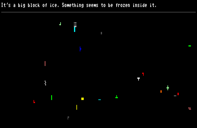
Last month’s Digest introduced robotfindskitten, a programming exercise that unites several major concepts of game programming: updating the display, reading user input, generating random values, timing events, and including and manipulating large amounts of static game data. I offered examples of each of these tasks in BASIC 65, and proposed that these could be used to make a robotfindskitten experience for the MEGA65.
In this issue, I want to start reviewing these topics again in assembly language. Without BASIC’s help, the program will need to turn to hardware registers and low-level programming techniques to achieve similar effects. Some of these topics are too large for a single newsletter, so we’ll take this in two parts. I’ll try to keep things simple by limiting this to just the needs of a robotfindskitten program. Applications that require higher speed or more memory may need more sophisticated techniques.
This month’s Digest will focus on using the KERNAL, printing messages, and drawing characters to the screen—barely scratching the surface of the MEGA65’s graphics capabilities. Next month, we’ll finish robotfindskitten in assembly language with random values, user input, item descriptions, and a simple animation delay.
Shipping update
The work continues to finalize the new R5 main board hardware for the next delivery batch of computers. Getting the test hardware has taken longer than anticipated, and we are now expecting manufacturing lead times to put the batch #3 delivery in early 2024.
Importantly, the team has decided to proceed with the full verification process for the new design, and not skip any steps just to accelerate the schedule. The MEGA65 is manufactured in small volumes in a not-for-profit operation, so we can’t afford to rush the process and risk having to re-make and replace hardware. We want every computer delivered to be as high in quality as possible.
Some pre-orders have been pending for a very long time now, and we thank you for your patience! If you have a pending pre-order and need to make changes, contact Trenz Electronic customer support.
Tristam Island

Tristam Island for the MEGA65.
Tristam Island, by Hugo Labrande, is a new text adventure game for multiple platforms, including the MEGA65. You can get the deluxe boxed edition, from publisher poly.play for 35 EUR. The deluxe edition includes the game on 3.5" floppy disk and on microSD card, a hint book, immersive props such as a rock sample and a postcard, and more. You can also get the digital-only edition for $3.99 USD.
Thanks to Hugo for the great game and for supporting the MEGA65, and to poly.play for publishing fun collectible boxed software for our favorite platform!
Updated ZX Spectrum core
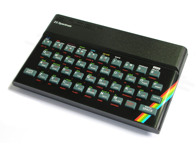
The ZX Spectrum.
Did you know that you can turn your MEGA65 into a ZX Spectrum? You can, with the ZX Spectrum core! This core just received a major overhaul to use the MiSTer2MEGA65 framework, and now works with modern displays.
Download the ZX Spectrum core from Filehost, then follow these detailed instructions for set-up and enjoyment. The core expects certain files in specific locations on the SD card, and uses ESXDOS v0.8.8 (not v0.8.9) for SD card access. It can load .tap and .trd files.
Once again thanks to sy2002 and MJoergen for their amazing work on setting up the MEGA65 for retro core success!
More arcade cores!
muse continues the great work of porting arcade game cores to the MEGA65. Bombjack (1984) (installation instructions) and Bosconian (1981) (installation isntructions) are both available.
The complete list of alternate cores for the MEGA65 so far:
Ports and enhancements by MJoergen and sy2002:
- Commodore 64 v5
- ZX Spectrum v1.0
- Game Boy v0.8
Ports and enhancements by muse (shoestring):
Along with a MEGA65 development core in slot 1 and a factory-installed stable core in slot 0, that’s more cores than there are core slots on a MEGA65! Just keep the .cor files on your SD card and flash them as needed.
Conference talks
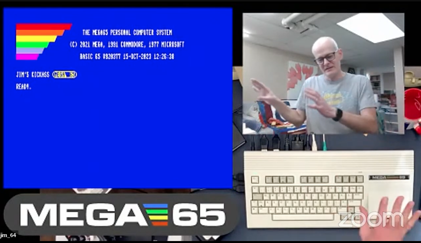
Jim Happel (jim_64) at Commodore Retro eXpo 2023
MEGA65 enthusiasts have been giving talks at computer conferences this year, and several of them now have video online. Check these out!
- Oliver Graf (lydon) at Vintage Computing Festival Berlin 2023
- Jim Happel (jim_64) at Commodore Retro eXpo 2023
- Dan Sanderson (dddaaannn) at Pacific Commodore Expo Northwest 2023
If you have given a presentation on the MEGA65, even just to your local computer club, and there’s video online, please let me know so I can feature it here!
robotfindskitten in assembly language
Let’s take a look at how you might implement robotfindskitten in MEGA65 assembly language. This month will focus on using the KERNAL API and manipulating the display. Next month, we’ll cover the remaining topics to get a robotfindskitten program working, similar to what we did in BASIC last month.
As before, I’ll be using the Acme assembler. Here’s a reminder of the starter code for an assembly language program that assembles to a PRG file that can be loaded and run. The !8 ... values describe a BASIC bootstrap program that invokes the first assembly language instruction.
!cpu m65
!to "rfk.prg", cbm

* = $2001

!8 $12,$20,$0a,$00,$fe,$02,$20,$30,$3a,$9e,$20
!pet "$2014"
!8 $00,$00,$00

start:
    ; Program code will go here.
Introducing the KERNAL
Every Commodore computer has a built-in operating system powered by machine code etched into the computer’s Read Only Memory (ROM). You see this code running as soon as you turn on the computer: the READY prompt, the blinking cursor, and the BASIC interpreter and all of the BASIC commands are all built-in code. Included in this code is a collection of machine code routines and subsystems for accessing hardware such as the keyboard, screen, and disk drives. In computer architecture terms, these routines are known as the kernel, the centerpiece of the system used by other components. Commodore employee Robert Russell originally misspelled the word “kernel” as “KERNAL” in the documentation, and this became a nickname for the software. For the sake of tradition, I’ll continue to refer to the Commodore kernel as the KERNAL, using uppercase letters.
A program can call KERNAL routines by way of a jump table, a list of jmp instructions built into the ROM at a fixed memory location. Each jmp instruction redirects to the actual location of the routine elsewhere in memory. The jump table exists to give programmers peace of mind that each jmp instruction will stay at a consistent address for all future revisions of the KERNAL. When changes in the KERNAL code inevitably push an internal routine to a new location, the jump table is updated accordingly, so programs that use the routine continue to function without needing an update.
Here’s a useful example. The KERNAL maintains a system for printing PETSCII codes to the screen. As we’ve seen before, these codes manipulate a cursor that determines the location of the next printable character, and maintains other properties such as the text color and display attributes. The BASIC PRINT command uses this system to display strings of codes and characters. Machine code programs can also access this system using a routine called chrout (also called bsout in some documentation), available via the jump table entry at $FFD2.
chrout = $ffd2

    lda #147      ; clear the screen
    jsr chrout

    lda #65       ; the letter "A"
    jsr chrout
The chrout routine has a pre-condition that the PETSCII code to print is in the accumulator (CPU register “A”). The effect of calling the routine is to print the PETSCII code at the current cursor position. If the code is a printable character, it plots the character, moves the cursor, and performs other effects like scrolling the display as needed. If the code is some other PETSCII code, such as code 147 to clear the screen and move the cursor to the top-left corner, that code takes effect.
The jump table is part of the Application Programming Interface, or API, of the KERNAL. The API definition also includes the pre-conditions and post-conditions of each routine, and other important behavioral characteristics about what the routine does. All KERNAL jump table entries designed for the C64 and C128 are valid on the MEGA65—with some changes. While neither the C65 nor the MEGA65 have introduced new table entries, future versions of the MEGA65 ROM could extend the table further without changing any of the existing entries.
It’s important to remember that the MEGA65 ROM is an active construction zone, and only some of the KERNAL APIs borrowed from previous Commodores are considered officially supported for now. Some things that C64 programmers may be used to aren’t official APIs, even if they appear to function today. When the dust has settled on the major bug fixes, the MEGA65 team will formalize more of the KERNAL API surface, adding documentation about supported features to the manuals and building automated tests to ensure that the APIs work properly. The KERNAL jump table is officially supported, as are certain specific facts about the memory layout, such as $2001 being the start address for BASIC programs.
Once a machine code program is running, it is not obligated to use the KERNAL. In fact, many games and larger utilities jettison the KERNAL entirely, installing custom interrupt handler routines, defining a custom memory map, and manipulating the computer entirely through hardware registers. For such a program, the only API surface is the hardware itself, and there is no need to integrate with the KERNAL except to launch the program. If the program does use KERNAL routines and systems, it must honor the KERNAL’s documented pre-conditions, and stay out of its way.
Printing a short message using the KERNAL
The following code uses the KERNAL chrout routine to clear the screen and print a short message:
    lda #147       ; clear the screen
    jsr chrout

    ldx #0
-   lda message,x  ; read a byte from message, offset by X
    beq +          ; if it's a zero, we have reached the end of the message
    jsr chrout     ; output the byte
    inx            ; increment X
    bra -          ; loop back
+   rts

message:
!pet 14,"robotfindskitten",0   ; Acme directive to generate PETSCII bytes
This example uses the “X indexing” addressing mode to access characters in the message stored in program memory. lda message,x takes the address of the message, via the assembler symbol message, and adds the value in the X register to it. The X register is one byte, with a range of possible values of 0 to 255. This limits the length of the message to 254 PETSCII codes and one 0 byte to indicate the end of the message.
There’s another way to print short messages, using another KERNAL routine. The primm routine at $FF7D will print a null-terminated message, with the message bytes immediately following the jsr instruction. It’s like having a PRINT command for assembly language!
primm = $ff7d

    jsr primm
!pet 14,"robotfindskitten",0

    ; Program continues...
It seems like a magic trick for the message bytes to be sitting in the middle of the code like this. How does the CPU know to skip over the message to the next instruction? The primm routine is quite clever. When the CPU encounters a jsr instruction, it remembers the address just after the instruction, so it can pick up where it left off when the subroutine exits with the rts instruction. The primm routine assumes that this address is the starting byte for the message and starts printing. When primm finds the 0, it updates the return address to just after the 0, then issues the rts. The CPU is blissfully unaware that primm has been messing with the return address and proceeds to execute the rest of the program. Pretty slick!
Note that primm is also limited to messages of 254 characters. To print a longer message, we need a different strategy.
Printing longer messages
In the code above, message is a symbol whose value is determined by the assembler and inserted into the code where the word appears. Wouldn’t it be great if we could update the value of the message symbol as the program executes, like a variable? The value of message is written into the machine code, and this code is just bytes in memory. One option is to update the address bytes within the code by writing to the appropriate memory locations, then execute the code. This technique, known as self-modifying code, is quite common, and not that difficult with a bit of care.
The following routine accepts the low byte and high byte of the message address in the Y and Z registers, and prints the message until it encounters a 0 byte. It relies on the knowledge that the lda $0000,x instruction assembles to three bytes: one for the instruction code, and two for the address. It uses the X register as before, but this time it tests whether X wraps around from 255 to 0, then increments the high byte of the address and continues printing. This gives us a maximum message length of 65,535 characters, which is more than enough.
    ldy #<intro_message
    ldz #>intro_message
    jsr print_long_message

; ...

print_long_message:
    ; Y,Z = address
    sty .load_selfmod+1
    stz .load_selfmod+2
    ldx #0
.load_selfmod
    lda $0000,x
    beq .end
    jsr chrout
    inx
    bne .load_selfmod
    inc .load_selfmod+2
    bra .load_selfmod
.end
    rts

intro_message:
!pet 147,14,5,27,"8"  ; clear, lowercase, white, 80x25
!pet "robotfindskitten in MEGA65 assembly language",13
!pet "Based on the game by the illustrious Leonard Richardson (C) 1997, 2000",13
!pet "Press Return to start.",0
Changing the cursor location
Another useful KERNAL routine for printing is the plot routine, at $FFF0. plot can do two things: it can either move the cursor to given coordinates, or it can report the coordinates of the cursor’s location. You use the carry flag to choose between the two actions. To move the cursor, clear the carry flag (clc), then set the X register to the column number and the Y register to the row number.
plot = $fff0

    clc
    ldx #12
    ldy #1
    jsr plot
To ask plot to report the current location, set the carry flag (sec) before calling it. Instead of changing the cursor position, plot will overwrite the values in the X and Y registers with the current cursor location.
A word of caution: When the KERNAL print system prints a character in the bottom-right corner of the screen, it assumes that more text needs to appear on the following line, and scrolls the text display to make room. When plotting characters for game graphics, this probably isn’t what you want. A simple albeit unsatisfying way to avoid this issue is to never print a character in the bottom-right corner.
Accessing screen memory
You could make a robotfindskitten game using just the KERNAL print system: use plot and chrout with PETSCII codes to draw items, and erase and draw the robot character as it moves across the screen. Most games don’t use the KERNAL print system to plot characters at all. Instead, they write directly to screen memory, color memory, and registers in the VIC-IV chip. This avoids issues like the KERNAL scrolling the text display, at the expense of doing other things manually, such as calculating memory locations for screen coordinates, and managing character attributes and colors.
If your program uses the KERNAL print routines, it’s best to let the KERNAL manage screen memory as much as possible. The KERNAL uses internal variables to keep track of some screen properties, and these need to be consistent with its own understanding of the state of the video hardware. If you change the screen mode or relocate screen memory via VIC-IV registers without telling the KERNAL, actions performed by PETSCII codes, such as clearing the screen, may not function correctly.
Handling screen memory is an essential skill for assembly language programmers. It’s also a deep topic. So let’s limit this discussion of screen memory to a few salient facts. To tell the KERNAL to set the screen mode to 80 x 25 text, print the Escape + 8 key sequence with chrout, as if you were typing it at the READY prompt:
    lda #27  ; Escape
    jsr chrout
    lda #'8' ; PETSCII "8"
    jsr chrout
If you’re not using the KERNAL, you can select the screen mode with flag registers at location $D031. To get 80 x 25, clear the V400 register (bit 3) and set the H640 register (bit 7). Without the KERNAL, you will need to write your own message printing routines that write directly to screen memory; you can’t use chrout.
The starting address of screen memory is in a VIC-IV register known as SCRNPTR, a 28-bit value stored at $D060-$D063, least significant byte first. The KERNAL will set this when you print the escape sequence for the screen mode. If you’re not using the KERNAL, you can set this to any address you like in the first 384K of memory by writing its address into the registers.
The KERNAL’s preferred memory location for a 40 x 25 or 80 x 25 screen is address $0800. Strictly speaking, this is not a documented fact: a program that relies on the KERNAL’s setting must read it from SCRNPTR, and never assume its value. For propriety, the examples below will read the SCRNPTR value instead of assuming it, but—at least for now—I’m also relying on the fact that the address is within bank 0 (addresses $0000 to $FFFF) so we can use 16-bit addressing modes and don’t have to worry about accessing upper memory. Note that this won’t work with 80 x 50 text mode, because the KERNAL relocates screen memory to bank 1 for this mode.
As with BASIC’s T@&() special array, screen memory contains screen codes that represent the characters in the character set. The codes are organized in columns then rows, from top-left to bottom-right: the first 80 bytes are the top row, the next 80 bytes are the next row, and so on, for 80 x 25 = 2,000 bytes.
The following example uses the self-modifying code technique to store a value in screen memory. The sta instruction can only operate on 16-bit addresses, so it uses the lower two bytes of SCRNPTR, and assumes the upper bytes are zero (an address in bank 0).
scrnptr = $d060

    ; Use self-modification to write to the (16-bit, bank 0) SCRNPTR address
    lda scrnptr
    sta store_screen_selfmod+1
    lda scrnptr+1
    sta store_screen_selfmod+2

    lda #1     ; Screen code for the letter A
store_screen_selfmod
    sta $0000
Color memory
In the regular text mode, color memory stores the foreground color and attributes for each character on the screen, organized in the same way. One way to access color memory is starting at address $D800.
There’s one issue, though. By default, only the first 1K of color memory is visible here, from $D800 to $DBFF. That’s not enough for all 2,000 characters of a 80 x 25 display! This is solved by yet another of the MEGA65’s many modes. The CRAM2K register, bit 0 of $D030, swaps the registers from $DC00 to $DFFF with the remaining color memory. To do this, it hides other hardware registers normally at those locations, such as the CIA chip registers. The KERNAL expects to see the registers here and not color memory, so you must clear the bit before calling KERNAL routines. (The KERNAL IRQ is smart enough to stash and restore your CRAM2K setting, so you do not need to disable interrupts. That’s a topic for another time.)
cram2k = $d030
color_mem = $d800

    lda #%00000001  ; Enable CRAM2K
    tsb cram2k

    lda #5          ; Paint the A green
    sta color_mem

    lda #%00000001  ; Restore registers
    trb cram2k
From coordinates to screen memory addresses
Given screen coordinates of column X and row Y, the offset into screen memory for that coordinate is Y times 80, plus X. The CPU doesn’t have an instruction that can multiple any two numbers, but it does have a quick and easy way to multiply a number by two: it can shift the bits of a number to the left, using the Arithmetic Shift Left instruction (asl). If it’s not clear that shifting the bits of a number to the left multiply it by two, write out a binary number, then write a zero at the end. For example, the binary number %0110 is 2 + 4 = 6 in decimal. Write a zero at the end, and it becomes %01100, which is 4 + 8 = 12 in decimal. Just as writing a zero at the end of a decimal (base ten) number multiplies the number by ten, writing a zero at the end of a binary (base two) number multiplies it by two.
Using a combination of left-shift and addition operations, we can calculate the screen memory address for a given set of coordinates in three steps:
- Calculate the row offset from the Y coordinate, stored in a memory variable (
row_offset), using bit shift and addition operations to multiply Y by 80. - Add the base address and the row offset, stored in the address part of a
sta ...,xinstruction (self-modifying code). - Use X-indexing with the X coordinate, to determine the final address and set the screen code.
row_offset: !byte 0,0

plot_char:
    ; Pre-condition:
    ; - A is the screen code
    ; - X register is the X coordinate
    ; - Y register is the Y coordinate

    taz         ; Stash the screen code in Z, so
                ; we can use A for other things

    lda scrnptr
    sta store_screen_selfmod+1
    lda scrnptr+1
    sta store_screen_selfmod+2

do_plot:
    ; - Z is the value to store in memory

    ; Calculate Y * 80 into row_offset memory variable
    lda #0
    sta row_offset+1 ; reset row_offset's high byte
    tya
    sta row_offset   ; store the row number as row_offset's low byte
    asl              ; x2
    asl              ; x4
    adc row_offset   ; x5
    sta row_offset
    asw row_offset   ; x10
    asw row_offset   ; x20
    asw row_offset   ; x40
    asw row_offset   ; x80

    ; Add row_offset to store_screen_selfmod+1
    lda store_screen_selfmod+1
    clc
    adc row_offset
    sta store_screen_selfmod+1
    lda store_screen_selfmod+2
    adc row_offset+1  ; add with carry
    sta store_screen_selfmod+2

store_screen_selfmod:
    stz $0000,x

    rts
To update color memory, the only difference in this routine would be to use a different base address, and set CRAM2K while updating memory. I added a do_plot label above so I could share the common code between the two routines.
color_char:
    ; Pre-condition:
    ; - A is the color
    ; - X register is the X coordinate
    ; - Y register is the Y coordinate

    taz        ; Stash the color code in Z, so
               ; we can use A for other things

    lda #<color_mem
    sta store_screen_selfmod+1
    lda #>color_mem
    sta store_screen_selfmod+2

    lda #%00000001  ; Enable CRAM2K
    tsb cram2k

    jsr do_plot

    lda #%00000001  ; Restore registers
    trb cram2k

    rts
Base Page Indirect Addressing
Each machine code instruction that accesses memory can operate in one or more addressing modes, ways for the CPU to figure out what address to use. We’ve seen three addressing modes in the examples so far:
Immediate mode: use the value given in the instruction. This example loads the number 7 from the instruction into the accumulator:
lda #7
Absolute mode: use the 16-bit address given in the instruction. This example loads the value stored at address $20CF into the accumulator:
lda $20cf
Absolute X-indexed mode: take the given 16-bit address, then add the value from the X register to it, and use that as the address. This example sets the X register to $2F, then loads the value stored at the address calculated as $20CF plus the value in the X register ($20CF + $2F = $20FE) into the accumulator:
    ldx #$2f
    lda $20cf,x
The X register can contain a value from 0 to 255, which limits the range of the X-indexed addressing mode. Earlier, I used self-modifying code to get around this problem, allowing for performing calculations on the entire address. The following example rewrites the 16-bit address portion of an instruction that’s using absolute mode addressing, then executes the modified instruction:
    lda #$cf
    sta .selfmod+1
    lda #$20
    sta .selfmod+2

.selfmod:
    lda $0000
Writing the address directly into an instruction like this is only really practical if only one instruction needs the address, and the modifying code knows exactly which address to modify. In many cases, it’d be better if we could store the address in one memory location like a variable, then tell the instructions where to find it.
Base Page Indirect Addressing mode can do exactly that. This example stores a 16-bit address at memory location $10-$11, then accesses it using the Y register as an index:
    lda #$cf
    sta $10
    lda #$20
    sta $11

    ldy #0
    lda ($10),y
So why didn’t I do this earlier? Well, there’s a catch: the address must be written to the base page, a region of 256 bytes that gets special treatment. Commodore 64 programmers know this as the zero page, within the addresses $0000 to $00FF. The CPU uses special forms of its instructions to access these addresses faster and with more compact code than absolute 16-bit addresses, so the base page is a great place to put variables. It’s so useful, in fact, that the KERNAL claims all of the zero page for its own use. If your program uses the KERNAL, you must protect the zero page so that it’s the way the KERNAL left it by the time you call a KERNAL routine.
With the original 6502 CPU, the base page is always at address $0000 (hence the name “zero page”). The 65CE02 CPU (on which the MEGA65’s 45GS02 is based) adds a feature that lets you use any 256-byte page of the first 64K of memory as the base page. The B register holds the top two nibbles (two hexadecimal digits) of the address of the base page. Your program can stake out its own base page and set the B register to that location to use it. I recommend page B = $16 ($1600 to $16FF), which is reserved for use by your program.
You must change B back to $00 before calling a KERNAL routine. The base page being set to $00 is a pre-condition of all KERNAL routines. (The B register is preserved along with other registers during interrupt handling, so you don’t have to worry about confusing the KERNAL IRQ.)
To set the B register, put the desired value in the accumulator, then use the tab instruction (Transfer A to B). If you need to read the B register, transfer it back to the accumulator first, with tba. The requirement to go through A to set or read B sometimes requires a bit of register wrangling.
Another register consideration to keep in mind: Base Page Indirect Addressing always uses an index register. The lda instruction supports using the Y or Z registers as indexes for this mode. If you just want to use the address directly, you must set the index register to 0.
Here’s another version of the long message printer using Base Page Indirect addressing, preserving the zero page for the KERNAL and using page $16 for the program’s base page. Try to follow which register has which value:
print_long_message_2:
    ; Y,Z = address
    lda #$16   ; A = $16
    tab        ; B = $16
    sty $00    ; $1600-$1601 = the message address
    stz $01
    ldy #0     ; Y = 0
.loop
    lda ($00),y  ; Load a character from the message address + Y
    beq .end     ; If the value is 0, end.
    tax          ; Stash the character in X so we can use A to set B.
    lda #0       ; A = 0
    tab          ; B = 0
    txa          ; A = the character
    jsr chrout
    lda #$16      ; A = 16
    tab          ; B = 16
    iny          ; Y = Y + 1
    bne .loop    ; If Y hasn't rolled over to 0, continue.
    inc $01      ; Y rolled over, so increment the high byte of the message address.
    bra .loop    ; Continue.
.end
    lda #0
    tab
    rts
This is not necessarily better than the earlier version using self-modifying code, especially with all the register flipping required. But it illustrates the use of base page variables as address pointers.
The 45GS02 CPU has another Base Page Indirect addressing mode, and it’s super useful: 32-bit Base Page Indirect Addressing lets you use a 32-bit address instead of a 16-bit address. With the Acme assembler in MEGA65 mode, this is indicated using square brackets instead of parentheses. Only the Z register is supported as the index in this mode.
    lda #$16
    tab

    ; Store the address $0001.F800 at base page address $00-$03
    lda #$00
    sta $00
    lda #$F8
    sta $01
    lda #$01
    sta $02
    lda #$00
    sta $03

    ; Store the value 7 at $0001.F800
    lda #7
    ldz #0
    sta [$00],z
Notice that other addressing modes do not support 32-bit addresses, so we can’t use the self-modifying code method to access upper memory, at least not in the same way. We can adapt the second version of the printing routine to be able to print long messages from anywhere in the MEGA65’s memory with minimal changes, but we can’t adapt the first version as easily.
Earlier, I made a potentially unsafe assumption that the KERNAL used an address between $0000 and $FFFF for SCRNPTR in 80 x 25 mode, and I just ignored the upper bytes of the SCRNPTR address. With 32-bit base page indirect addressing, I don’t have to do that: I can just copy the entire address from SCRNPTR to a four-byte base page variable, then use 32-bit indirect addressing to access screen memory.
Incidentally, upper memory addresses $1.F800 through $1.FFFF are another way to access the first 2K of color memory, with no need to set the CRAM2K flag. In my implementation of robotfindskitten, I use base page $16 for variable storage, and base page indirect addressing for plotting characters with the full four-byte SCRNPTR address and for plotting colors to 1.F800. I set the B register to $16 at the beginning of the program, and wrap my KERNAL calls to set B to $00 before the call and set it back to $16 afterward.
As you can see, there are multiple ways to accomplish certain tasks. For high speed applications, you may need to make your choices based on the amount of CPU time each operation takes, measured in CPU cycles. Instruction cycle counts are listed in the manual. robotfindskitten is not speed critical, so I just went with what made my code easiest for me to understand.
That’s a good start. With the KERNAL output routines and screen memory access, we have the tools to replicate BASIC’s PRINT, T@&(), and C@&() facilities in assembly language. Next month, we’ll look at another important KERNAL facility for accepting keyboard input, and some snazzy MEGA65 hardware features for generating random numbers and measuring time. We’ll close by designing data structures to access all of the item descriptions, and prevent two items from landing on the same place on the screen.
For comparison and enjoyment, here’s my BASIC version of robotfindskitten. It’s faithful to Leonard Richardson’s version, which is not particularly creative of me, but hopefully it serves as a useful reference implementation.
- rfk-bas.prg : robotfindskitten in BASIC 65; BASIC source code in petcat format
Happy coding! See you next month.
— Dan